Multifunctional photoelectric detection instrument and target position observing and determining method implemented by same
A photoelectric reconnaissance and multi-functional technology, applied in the field of photoelectric reconnaissance, can solve the problem of insufficient ability of single-person reconnaissance information acquisition, and achieve the effect of solving insufficient acquisition ability, good portability and flexibility, and compact structure size
- Summary
- Abstract
- Description
- Claims
- Application Information
AI Technical Summary
Problems solved by technology
Method used
Image
Examples
Embodiment 1
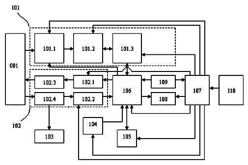
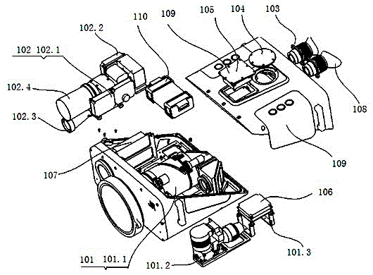
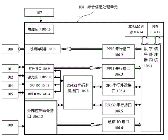
[0052] Example 1: Such as figure 1 , 2 Shown is a basic embodiment of a multifunctional photoelectric reconnaissance instrument of the present invention, which includes a cooling infrared sensor 101 located at the front end of the whole machine for recording an infrared image target 001, and a laser rangefinder for measuring the distance of the target 102, a visible light channel 103 for visible light observation, a GPS module 104 for detecting the position coordinates of the observation point, a magnetic compass 105 for detecting the horizontal angle and pitch angle of the target; there is also an integrated information processing unit 106, It is used to calculate the position information of the target, perform video encoding and enhancement processing on the image signal, synthesize and display the infrared image and information data, and control each component; there is also an input terminal connected to the battery 110 and an output terminal connected to the power suppl...
Embodiment 2
[0053] Example 2: It is a further embodiment based on Embodiment 1. In the multifunctional photoelectric reconnaissance instrument, its cooled infrared sensor 101 includes an infrared detector 101.2, and a target surface for converging infrared radiation on the infrared detector 101.2. An infrared optical system 101.1, an infrared detector 101.2 converts the infrared radiation signal into an analog electrical signal; an infrared imaging circuit component 101.3 is used to process the analog electrical signal, and complete the functions of AD conversion, non-uniform correction and bad element elimination, and then convert the The digital image signal is output to the integrated information processing unit 106, and at the same time, the working bias signal is sent to the infrared detector 101.2 to support the work of the infrared detector 101.2; the infrared optical system 101.1 is located on the target surface of the infrared detector 101.2 In the front, the infrared detector 1...
Embodiment 3
[0054] Example 3: It is a further embodiment on the basis of Embodiment 2. The laser range finder 102 of the multifunctional photoelectric reconnaissance instrument includes a laser emitting module 102.1 for emitting a laser that is safe for human eyes; a laser receiving module 102.2 for Receive the returned laser beam, convert the laser beam into an electrical signal, process it, and then send the processed electrical signal to the integrated information processing unit 106 to obtain target distance information; a transmitting optical channel 102.3 is used to transmit the transmitted The laser beam makes the laser beam more concentrated; a receiving optical channel 102.4 is used to receive the laser beam reflected by the target 001 and converge it to the laser receiving module 102.2. At the same time, it is used to receive and transmit visible light and share the optical path with the visible light channel 103 to Visible light channel 103 for long-distance observation; the ...
PUM
 Abstract
Description
Claims
Application Information
 - R&D
- Intellectual Property
- Life Sciences
- Materials
- Tech Scout
- Unparalleled Data Quality
- Higher Quality Content
- 60% Fewer Hallucinations
Browse by: Latest US Patents, China's latest patents, Technical Efficacy Thesaurus, Application Domain, Technology Topic, Popular Technical Reports.
© 2025 PatSnap. All rights reserved.Legal|Privacy policy|Modern Slavery Act Transparency Statement|Sitemap|About US| Contact US: help@patsnap.com


