
Rotary pivot bearing used for driving by shield spiral machine

A shield screw machine, pivot bearing technology, applied in the field of bearings, can solve the problems of complex force at the support, impact force of the drive bearing, uneven pressure of the muck, etc. Effect

Inactive Publication Date: 2012-10-24
JIANGSU KAIGONG TUNNEL MACHINERY +1
View PDF7 Cites 7 Cited by
  • Summary
  • Abstract
  • Description
  • Claims
  • Application Information

AI Technical Summary

Problems solved by technology

[0003] The screw conveyor is generally installed at a certain angle to lift up the muck from the bottom of the sealed chamber and transport it to the discharge point of the belt conveyor; the support of the screw rod generally adopts the single-point cantilever support method at the drive bearing at the output end of the reducer; the screw conveyor When the machine is working, the force on the supporting part of the driving bearing is relatively complicated. There are not only the thrust and reverse thrust formed by the muck pressure in the housing on the supporting part during forward and reverse rotation, but also the uneven pressure of the muck and the mixed sand and gravel in the muck. The rod swings relative to the rotating shaft, thereby forming an impact force on the drive bearing, seriously affecting the service life of the bearing, and causing certain hidden dangers to the smooth progress of construction

Method used


Image

  • Rotary pivot bearing used for driving by shield spiral machine
  • Rotary pivot bearing used for driving by shield spiral machine
  • Rotary pivot bearing used for driving by shield spiral machine

Examples


Embodiment

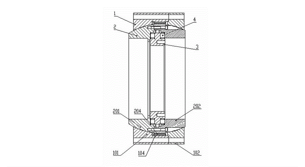
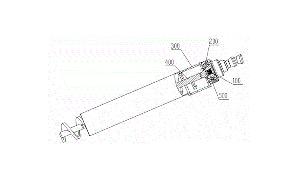
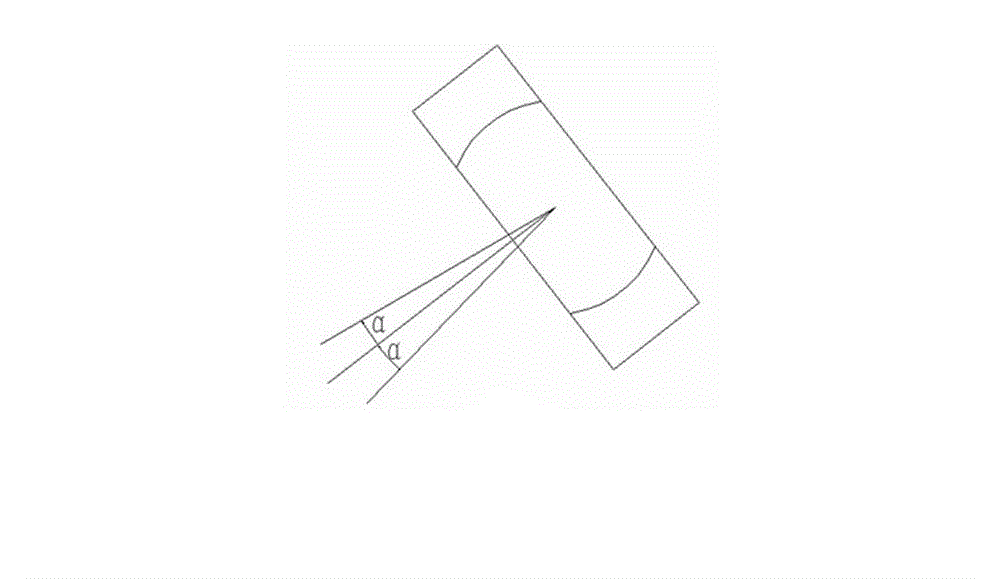
[0017] Embodiment: A rotary pivot bearing for driving a shield screw machine, including an outer ring 1, a middle ring 2, an inner ring 3 and a roller 4, the inner ring 3 can rotate in the circumferential direction and the axial stop is positioned in the middle In the ring 2, there is a raceway for the roller 4 to be accommodated between the inner ring 3 and the middle ring 2. The roller 4 can be rolled and positioned in the raceway, and the middle ring 2 is stopped in the circumferential direction and can rotate in the axial direction. The setting angle α is inserted in the outer ring 1. During operation, the rotating pivot bearing 200 is fixed on the casing 300 of the screw machine, and the inner ring 33 is respectively connected to the screw rod 400 and the output end 100 of the screw machine motor reducer through the connecting flange 500. In this way, the output end of the motor reducer drives the connecting flange 500, the inner ring 33 and the screw rod 400 to rotate aro...


PUM


Abstract

The invention discloses a rotary pivot bearing used for driving by a shield spiral machine, which comprises an outer ring, an intermediate ring, an inner ring and a roller, the peripheral direction of the inner ring can be rotationally and axially positioned in the intermediate ring, a raceway used for accommodating the roller is provided between the inner ring and the intermediate ring, the roller can be positioned in the raceway in a rolling mode, the peripheral direction of the intermediate ring is chocked and is capable of axially rotating a setting angle to insert in the outer ring. According to the invention, a rotating shaft is allowed to possess offset value with a certain angle, thereby the impact caused by a spiral machine due to the swing of a screw rod during the operation can be reduced, the usage period of a bearing driven by the spiral machine can be substantially increased, the roller of the bearing employs a three-row roller form, so that the axial thrust and the reverse thrust caused by muck pressure on the bearing can be born when the spiral machine utilizes the positive and negative rotation, and the radial force generated by overturning moment which is generated by swing and deadweight of the rotating shaft of the screw rod on the bearing can be born, the outer ring and the intermediate ring employ a separate structure, thereby assembling and dismounting processes can be conveniently carried out.

Description

technical field [0001] The invention relates to a bearing, in particular to a rotating pivot bearing for driving a shield screw machine. Background technique [0002] The screw conveyor is an important part of the soil discharge system of the earth pressure balance shield machine. During shield tunneling construction, the screw conveyor not only has the function of removing the dregs on the excavation surface, but also controls the pressure of the sealed chamber to maintain the earth pressure balance. The screw machine discharges the soil cut by the cutter head from the shield sealed chamber, and the soil is conveyed and compressed by the screw rod to form a sealed soil plug, forming a certain resistance, which can stabilize the soil pressure in the sealed chamber within a predetermined range . [0003] The screw conveyor is generally installed at a certain angle to lift up the muck from the bottom of the sealed chamber and transport it to the discharge point of the belt co...

Claims


Application Information

Patent Timeline
IPC IPC(8): F16C23/08F16C33/58
Inventor 苏延奇韩真杨凤林
Owner JIANGSU KAIGONG TUNNEL MACHINERY
Learn More