
Radial-flow magnetic wastewater separative purification equipment

A magnetic separation and radial flow technology, applied in the field of magnetic separation, can solve the problems of equipment cost, unoptimized floor space, equipment can not operate normally, low impact load resistance, etc., to achieve good separation and purification effect, The effect of high magnet utilization and strong shock load resistance

Active Publication Date: 2012-10-24
CHENGDU YUANRONG ENVIRONMENTAL TECH +1
View PDF10 Cites 10 Cited by
  • Summary
  • Abstract
  • Description
  • Claims
  • Application Information

AI Technical Summary

Problems solved by technology

[0004] The above-mentioned disc-type magnetic separation and purification equipment has the advantages of large water treatment capacity and smaller floor space than traditional methods due to its fast magnetic adsorption speed and large adsorption surface. The cost of equipment and the occupied area are not optimal
[0008] (3) The slag scraping part is set above the liquid level, so the equipment has low impact load resistance, especially when the water volume fluctuates greatly, the slag scraping part is submerged, and the equipment will not operate normally

Method used


Image

  • Radial-flow magnetic wastewater separative purification equipment
  • Radial-flow magnetic wastewater separative purification equipment
  • Radial-flow magnetic wastewater separative purification equipment

Examples


Embodiment 1

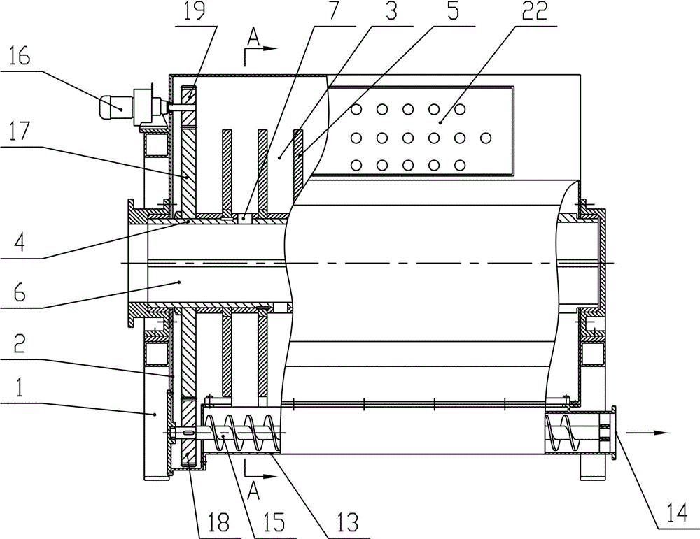
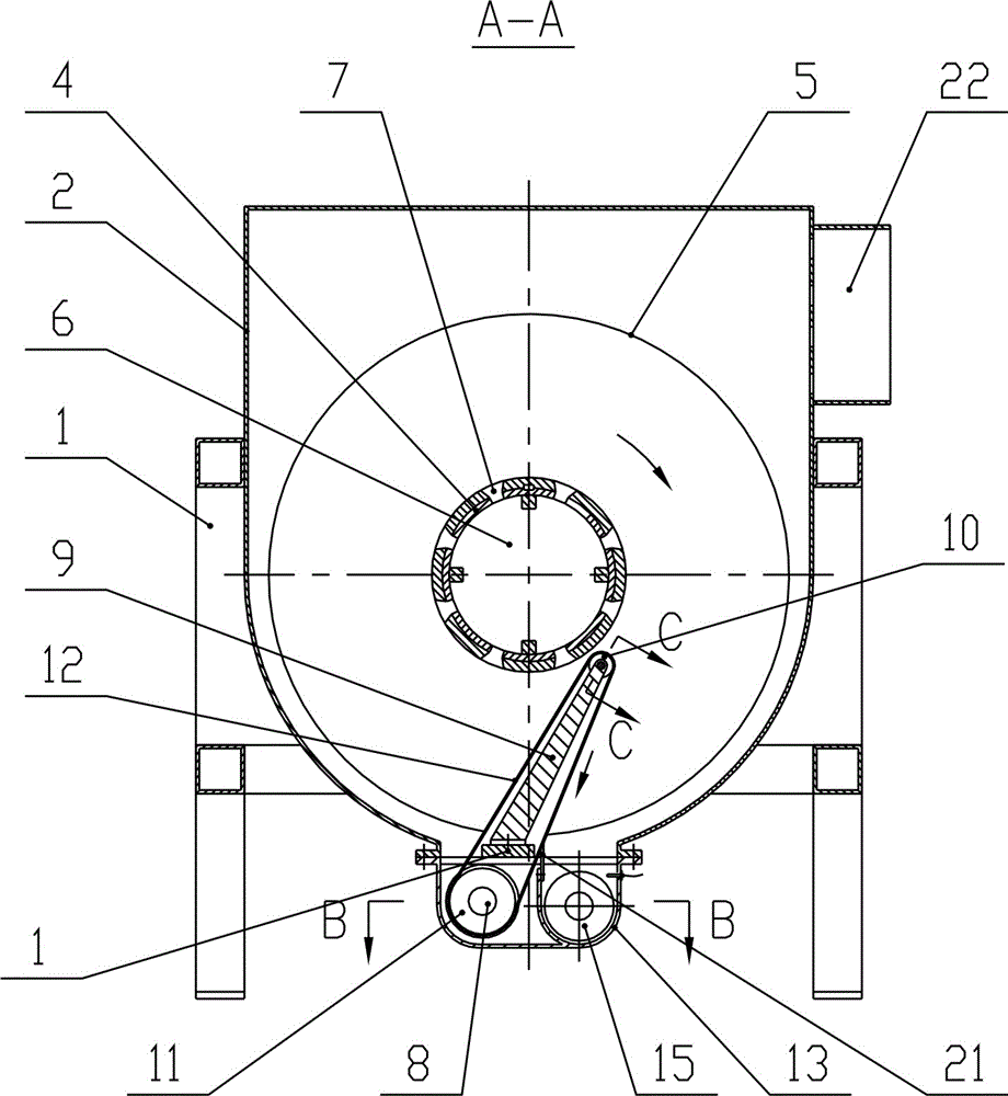
[0033] Such as figure 1 As shown, a radial flow magnetic force separation and purification wastewater equipment includes a frame 1, a water tank 2 arranged on the frame 1, a fluid interface 22 arranged on the water tank 2, a slag scraping mechanism and a transmission mechanism; a hollow shaft 4 The bearing seat is arranged in the water tank 2, and the hollow shaft 4 is provided with a number of disks 5 distributed at equal intervals; one end of the hollow shaft 4 is open, and the open end and the external pipe are a dynamic seal structure, which realizes the connection between the rotating hollow shaft 4 and the stationary The sealing fit between the external pipes; the hollow shaft 4 is arranged with a number of through holes 7 communicating with the hollow shaft cavity 6 .

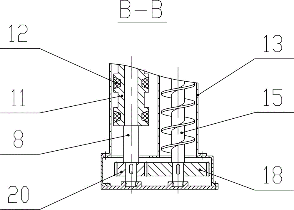
[0034] recombine figure 2 , image 3 as well as Figure 4 As shown, the slag scraping mechanism includes a slag scraping assembly and a slag conveying assembly. The slag scraping assembly is matched wi...

Embodiment 2

[0040] The structure of this embodiment is roughly the same as that of Embodiment 1, the difference is that the hollow shaft 4 is open at both ends, the two open ends and the external pipe are dynamic sealing structures, and the two ports can be used as water inlets or simultaneously as Use at the water outlet.


PUM


Abstract

The invention discloses radial-flow magnetic wastewater separative purification equipment which comprises a frame, a water tank, a fluid connector, a residue scraping mechanism and a transmission mechanism, wherein the fluid connector, the residue scraping mechanism and the transmission mechanism are arranged on the water tank which is disposed on the frame. The equipment is characterized in thata hollow shaft is arranged in the water tank through a bearing block and provided with a plurality of magnetic disks, at least one end of the hollow shaft is open, and the open end and an external pipeline are in a dynamic sealed structure. The hollow shaft is provided with a plurality of through holes communicated with a cavity channel of the hollow shaft, and the residue scraping mechanism comprises a residue scraping component and a residue conveying component. Compared with existing semi-immersed disk type magnetic separators in advection or streaming modes, the equipment has the advantages that fully-immersed operation of magnetic disks is realized by means of radial flows, is lower in investment cost, smaller in occupied area, high in impact load bearing capacity and lower in energyconsumption, and is new-generation disk type magnetic separative purification equipment.

Description

technical field [0001] The invention provides a radial flow magnetic force separation and purification equipment for waste water, which belongs to the technical field of magnetic separation. Background technique [0002] Magnetic separation technology is widely used in the separation of magnetic substances from fluids, such as the separation and removal of magnetic substances in ore selection, the purification of iron-containing metallurgical wastewater, etc. Common magnetic separation equipment includes magnetic drums, magnetic rollers, and disc magnetic separators. The basic principle is two-step separation: first, use magnetic force to absorb magnetic substances in the fluid, and then rely on gravity, hydraulic or mechanical forces (such as scrapers) to make them separate. The magnetic object breaks away from the magnetic field. [0003] In the field of wastewater treatment, as early as the 1970s in foreign countries, disk magnetic separators were used for the purificati...

Claims


Application Information

Patent Timeline
Patent Type & Authority Applications(China)
IPC IPC(8): C02F1/48
Inventor 谭国安
Owner CHENGDU YUANRONG ENVIRONMENTAL TECH
Learn More