Vacuum dust collector

A technology for vacuum cleaners and dust collectors, applied in the installation of vacuum cleaners, suction filters, electrical equipment, etc., can solve the problems of large space occupation, low utilization rate, large living space, etc. The effect of handling and improving the standardization rate

Inactive Publication Date: 2012-10-24
向桂南
View PDF1 Cites 0 Cited by
  • Summary
  • Abstract
  • Description
  • Claims
  • Application Information

AI Technical Summary

Problems solved by technology

[0004] In the horizontal vacuum cleaner, it is divided into a dust bag vacuum cleaner and a dust cup vacuum cleaner. Usually, the dust bag vacuum cleaner includes an upper cover, a middle frame and a base, a motor that provides a vacuum source, an air inlet for dust collection, and an air outlet for exhaust. Dust bag, vacuum brush attachment, etc. When the dust bag needs to be replaced, the upper cover can be opened to load or take out the dust bag. The upper cover can only be opened at a limited angle. The entire vacuum cleaner has a complex structure and is inconvenient to operate.
Also in the dust cup vacuum cleaner, it is divided into the middle frame and base forming the body, the motor that provides the vacuum source, the air inlet for dust collection and the air outlet for exhaust, the dust collection bucket, the attachment of the dust collection brush, etc. The dust collection bucket is usually Put it obliquely on the body of the vacuum cleaner, and the dust collection bucket can be taken out when in use. Because of this structure, the air intake duct of the vacuum cleaner, the air intake duct of the dust collection bucket, and the air intake duct of the motor are not in a straight line, and the air duct is bent And it is long, which greatly affects the suction of the vacuum cleaner. If the dust collecting bucket is erected on the body of the vacuum cleaner, the entire vacuum cleaner will be very high, the structure layout is not compact, and the space will take up a lot
[0005] Based on the above, in terms of structural design of vacuum cleaners, especially horizontal vacuum cleaners, due to their complex structure and changeable shapes, it brings great difficulties to standardized design, and is the product with the lowest degree of standardization among household appliances; and due to the spatial layout of vacuum cleaners The needs of the vacuum cleaner are often relatively large in size, and a series of hoses, hard pipes, and vacuum accessories are added to make the shape of the vacuum cleaner irregular, which brings great inconvenience to the storage of the vacuum cleaner and takes up a large amount of living space. At the same time, the use function of the vacuum cleaner is also very single. It is far inferior to the mop in terms of floor cleaning ability and use. Most Chinese families only use vacuum cleaners to suck dust from gaps in doors, windows, sofas, etc., so the usage rate in Chinese families is very low. , according to the survey, more than 90% of Chinese families do not use vacuum cleaners
[0006] The Chinese Patent Publication No. 102113852A discloses a vacuum cleaner, which can coil the vacuum hose on the vacuum cleaner body, and is provided with a plurality of clips for placing accessories, brushes, etc. at the rear of the vacuum cleaner. The accessories are integrated on the body of the vacuum cleaner, which is convenient for transportation and storage. However, since the accessories are still exposed outside, the accessories are often worn during transportation, which shortens the service life of some accessories. Moreover, such structural adhesives are complicated. , unstable
[0007] Chinese patent 200710131566.8 discloses an automatic vacuum cleaner with a remote control. It stores the remote control of the automatic vacuum cleaner on the vacuum cleaner body, which is convenient for storing and storing the remote control when the vacuum cleaner is not in use. However, it cannot solve the problem of making the vacuum cleaner compact and easy to store. The problem

Method used


Image

  • Vacuum dust collector
  • Vacuum dust collector
  • Vacuum dust collector

Examples


Embodiment Construction

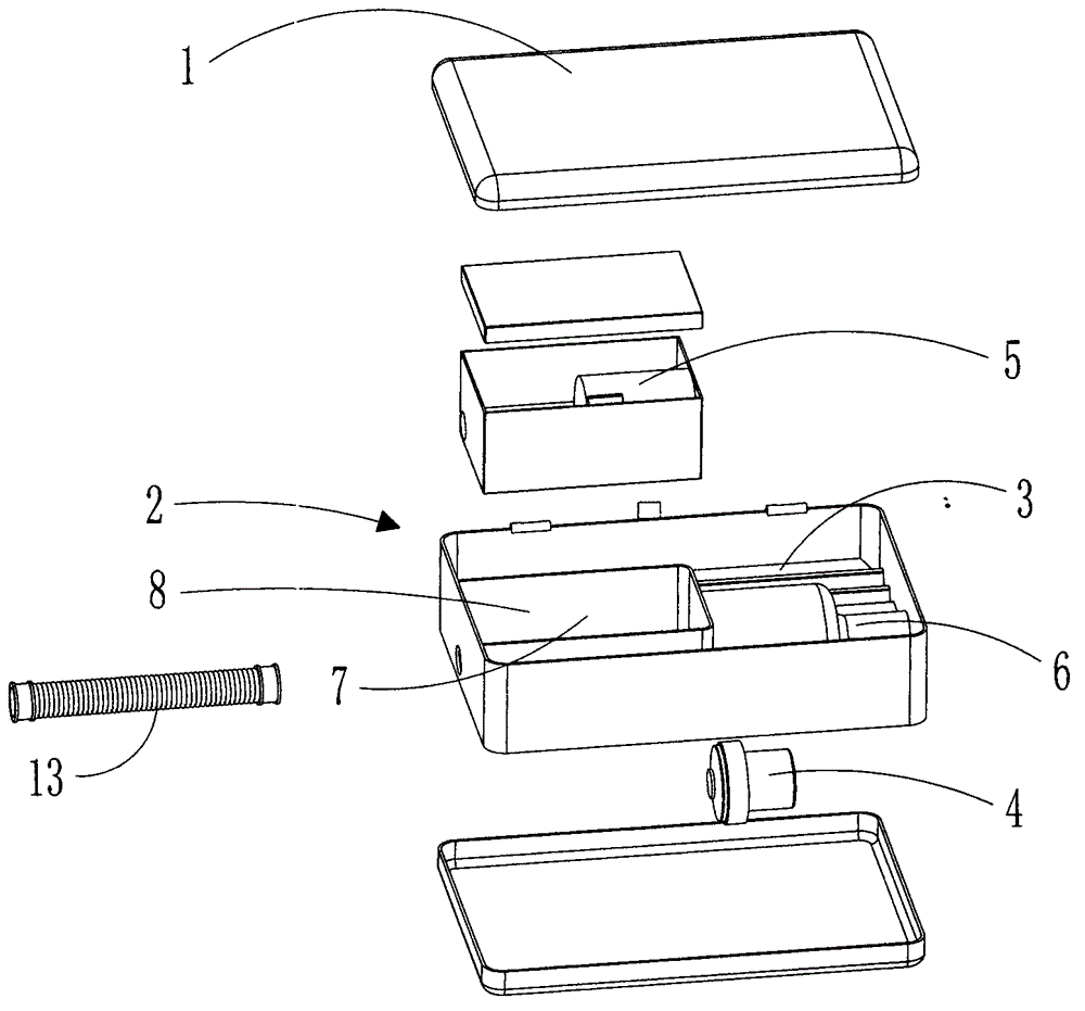
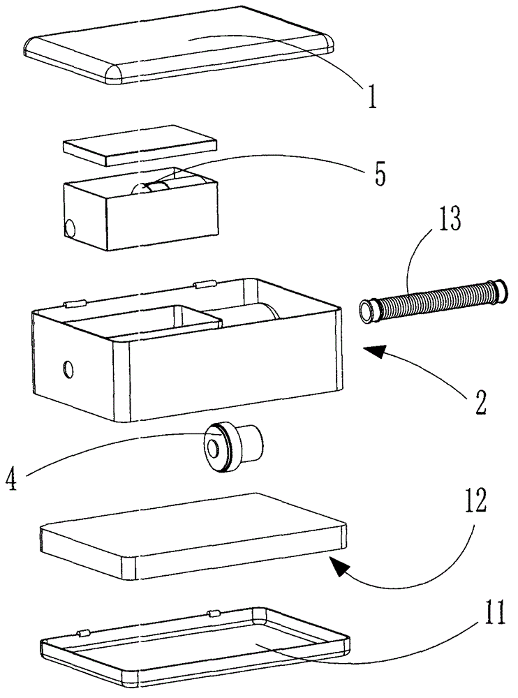
[0032] The present invention will be described in detail below in conjunction with the embodiments shown in the accompanying drawings. figure 1 The upper and lower positional relationship shown in this manual corresponds to the "upper" and "lower" positional relationships described in this manual:

[0033] As attached figure 1 Attached Figure 4 As shown, the vacuum cleaner of the present invention includes a vacuum cleaner body and an accessory that is detachably connected to the body. The body includes an upper cover 1, a housing 2, and a vacuum motor 4, a dust collector 5, and an inlet provided in the housing 2. The air channel 6 and the air outlet channel 7, the housing 2 is provided with a partition 3 transversely, and the lower part of the partition 3 is used to house the vacuum motor 4, the dust collector 5, the air inlet channel 6 and the air outlet channel 7. A space 8, the upper surface of the partition 3 and the lower surface of the upper cover 1 form a first storage sp...


PUM


Abstract

The invention discloses a vacuum dust collector, which comprises an upper cover, a shell, and a dust collecting motor, a dust collector, an air inlet channel and an air outlet channel which are arranged in the shell, wherein a separating part is transversely arranged in the shell; the lower part of the separating part forms a first space for accommodating the dust collecting motor, the dust collector, the air inlet channel and the air outlet channel; the upper part of the separating part forms a first storage space for storing articles; the lower part of the separating part forms a suction cavity; and a position on a side wall of the shell, corresponding to the dust collector, is provided with an air inlet, and a side wall of the opposite side is provided with an air outlet. According to the structure, the whole vacuum dust collector becomes a whole shell, the size of the vacuum dust collector is reduced, the storage space is enlarged, and the accessories of the vacuum dust collector and tools for daily life can be conveniently stored; and moreover, the shell can be made into a square, a circle, an ellipse and a D shape according to the requirements, the design of the vacuum dust collector is simplified, and the vacuum dust collector is fashionable in appearance.

Description

Technical field [0001] The invention relates to a vacuum cleaner. Background technique [0002] As we all know, the vacuum cleaner industry has grown into a fast-moving consumer goods industry, and the competition has become increasingly fierce. With the increasing development of science and technology, the structure and appearance of vacuum cleaner development in recent decades have been increasingly challenged. [0003] Generally, vacuum cleaners are divided into vertical vacuum cleaners, horizontal vacuum cleaners, hand-held vacuum cleaners and bucket vacuum cleaners. They usually include a body that constitutes an outer shell, a dust bag or a dust cup for collecting dust, and a vacuum source that provides a vacuum. The power supply is composed of a power cord for supplying power, a floor brush for sucking dust, a hose, a handle and accessories for holding. [0004] The horizontal vacuum cleaners are divided into bag type vacuum cleaners and dust cup type vacuum cleaners. General...

Claims


Application Information

Patent Timeline
Patent Type & Authority Applications(China)
IPC IPC(8): A47L9/00A47L9/10A47L9/28
Inventor 向桂南
Owner 向桂南
Why Eureka
Try Eureka