
Material charging and vibratory material feeding device with adjustable inclination angles

The technology of a feeding device and a driving device is applied in the field of metallurgy, which can solve the problems of adding links and equipment in the production of electric furnace logistics system, and the end openings of scrap steel and other materials slipping off, increasing the operations of pin loading and pulling pins, etc., so as to achieve improved safety performance, Save operation time and reduce the effect of auxiliary operations

Active Publication Date: 2014-07-02
中国冶金科工股份有限公司
View PDF9 Cites 0 Cited by
  • Summary
  • Abstract
  • Description
  • Claims
  • Application Information

AI Technical Summary

Problems solved by technology

However, in the actual production and operation process, the material trough of the patent application needs to go through the links of loading, transportation and lifting. In these links, if the method of tilting the long hopper is used for loading, transportation and lifting, The problem is that scrap steel and other materials are easy to slip through the end opening, which brings potential safety problems in production
In order to solve this problem, this patent application adopts the technical scheme of adding a stopper pin at the discharge port of the trough. Although this scheme can prevent materials such as scrap steel from slipping from the end opening of the trough to a certain extent, in actual production , this solution will add pin loading and unplugging operations to the production process, adding additional links and equipment to the production of the electric furnace logistics system, affecting production efficiency (delaying the tapping cycle by 3 to 6 minutes)

Method used


Image

  • Material charging and vibratory material feeding device with adjustable inclination angles
  • Material charging and vibratory material feeding device with adjustable inclination angles
  • Material charging and vibratory material feeding device with adjustable inclination angles

Examples


Embodiment Construction

[0025] The specific implementation manners of the present invention will be described in detail below in conjunction with the accompanying drawings.

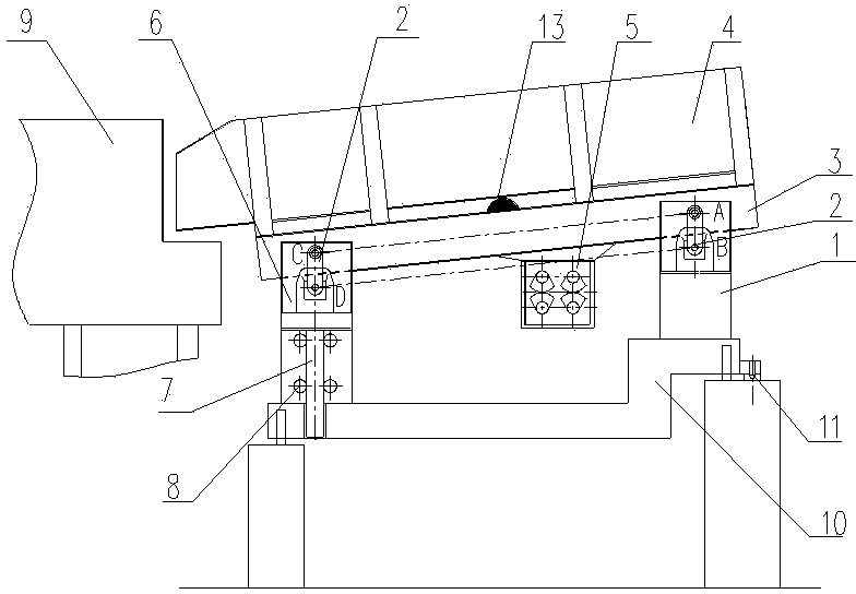
[0026] Such as figure 1 as shown, figure 1 It is a schematic structural diagram of an embodiment of the tilt-adjustable charging and vibrating feeding device of the present invention, specifically showing that the long hopper is in the tilting feeding position.

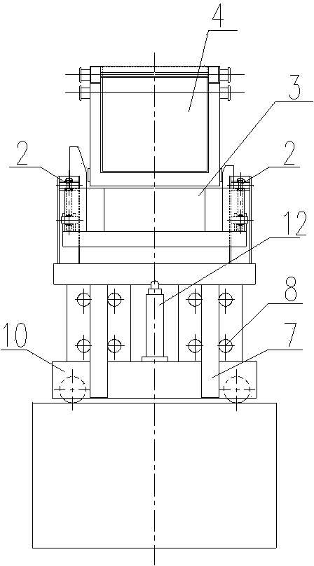
[0027] The charging and vibrating feeding device with adjustable inclination of the present embodiment comprises a vibrating table 3, a long material trough 4 installed on the vibrating table 3 and an inclination adjusting device for adjusting the inclination angle of the long material trough 4, and the inclination adjusting device includes a vibrating Table 3 is hingedly connected with a length-adjustable elevating frame 6 and a driving device corresponding to elevating frame 6 and used to drive elongating and shortening elevating frame 6 . The driving device can be ...


PUM


Abstract

The invention discloses a material charging and vibratory material feeding device with an adjustable inclination angle, comprising a vibrating table and a long material tank arranged on the vibrating table, further comprising an inclination angle adjusting device used for adjusting the inclination angle of the long material tank, wherein the inclination angle adjusting device comprises a driving device arranged correspondingly to a lifting frame with an adjustable length, and used for driving the lifting frame to extend and contract; and the lifting frame is hinged with the vibrating table by a double-hinge connection rod. With the adoption of the inclination angle adjusting device, the material charging and vibratory material feeding device with the adjustable inclination angle has the advantages that the inclination of a discharge opening of the long material tank is adjusted conveniently according to actual need in the continuous material charging process of the electric furnace by the long material tank, so as to avoid the materials such as waste steel falling from the discharge of the long material tank, in this way, the security is greatly enhanced, the assistant operation for preventing the materials falling from the discharge opening of the long material tank is reduced, so the operation time is saved, and the production efficiency is improved.

Description

technical field [0001] The invention belongs to the technical field of metallurgy, and in particular relates to a charging and vibration feeding device with adjustable inclination, which is used for realizing continuous feeding to an electric furnace. Background technique [0002] The continuous feeding of scrap steel is particularly important to ensure the efficiency and safety of the continuous feeding process of the electric furnace, and it is also an important energy-saving and environmental protection technology in the electric furnace steelmaking technology. At present, the most typical and common method in the production of electric furnaces at home and abroad is to use the material basket to directly feed the furnace hall, but the production environment is extremely harsh and consumes a lot of power; When feeding some raw materials, it is very difficult to implement the closed feeding technology of the electric furnace, and the reliability of the implementation is al...

Claims


Application Information

Patent Timeline
Patent Type & Authority Patents(China)
IPC IPC(8): F27D3/00
Inventor 黄其明高瞻
Owner 中国冶金科工股份有限公司
Learn More