
Automatic judgement method for pipe explosion and water leakage of solar water heating system

A solar water heating and automatic judgment technology, applied in the field of solar thermal utilization, can solve the problems of misjudging the explosion of the pipe and the failure of the electrodes to form a current loop.

Inactive Publication Date: 2012-10-17
北京创意博能源科技有限公司
View PDF1 Cites 4 Cited by
  • Summary
  • Abstract
  • Description
  • Claims
  • Application Information

AI Technical Summary

Problems solved by technology

Since the top of the collector is the place with the highest temperature in the collector, a large amount of scale will be deposited there, including on the electrodes. In the end, due to the thick scale, the current loop cannot be formed between the electrodes and the alarm will be misjudged.

Method used


Image

  • Automatic judgement method for pipe explosion and water leakage of solar water heating system
  • Automatic judgement method for pipe explosion and water leakage of solar water heating system
  • Automatic judgement method for pipe explosion and water leakage of solar water heating system

Examples


specific Embodiment 1

[0042] A solar water heating system using temperature difference circulation.

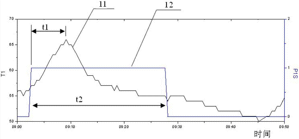
[0043] During normal operation as image 3 As shown, at 9:02:38, the water pump starts to start the temperature difference cycle, and the temperature at the collector outlet starts to rise from 57°C. At 9:09:08, the temperature reaches the highest point of 66°C, and then the collector outlet temperature begins to drop. , until 9:28:08, the water pump stops running, and the temperature at the outlet of the collector is 54°C. It can be calculated that the time t1 at which the temperature peak appears is 7.5 minutes.

[0044] like Figure 4 As shown, the solar hot water system has water leakage from the fried pipe. Since the water leakage is not very large, the water temperature can still rise after the water pump is started. The time when the water pump starts is 14:44:55, and the time when the temperature reaches the highest It is 15:00:54, and the time t1 to reach the highest peak is 16 minutes,...

specific Embodiment 2

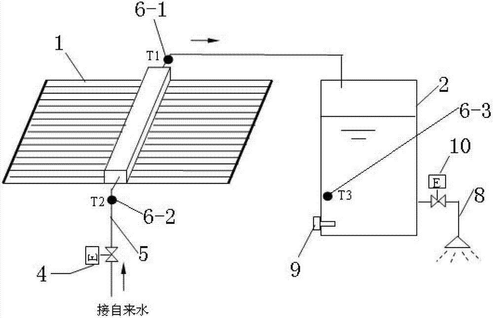
[0045] A solar hot water system adopts the constant temperature water outlet method. When the solenoid valve is opened, the time t1 for the peak temperature of the collector outlet is 3 minutes, and the water level of the water tank rises at a speed of 70-76mm / min. When there is water leakage from the fried tube, the peak time t1 of the outlet temperature of the collector reaches 10 minutes, and the water level of the water tank rises at only 22mm / min.

specific Embodiment 3

[0046] For solar hot water systems with multiple collector arrays and multiple circulation loops, the constant temperature water outlet operation mode is often used when the water tank is not full. When the water tank is full, it is changed to the temperature difference circulation mode. When the water consumption is less than 50%, Then change to the constant temperature outlet water operation mode. It is necessary to record and compare the normal values ​​according to the outlet temperature of each collector array and the status of the water pump and solenoid valve, and then judge which collector is the current one according to the current operating mode (temperature difference cycle or constant temperature water outlet). There was water leakage from the frying tube in the heater display.


PUM


Abstract

The invention discloses an automatic judgment method for pipe explosion and water leakage of a solar water heating system; firstly, when the solar water heating system is installed to operate normally, and when a solar collector is started through circulation of temperature difference and water yielding at a constant temperature, changes of such parameters as temperature of the solar heater outlet, water level of a water tank, time for reaching a peak water temperature, temperature rise amplitude, cooling time, circulation time and the like are recorded; then, when a water circulating pump or an upper water solenoid valve of a solar thermal collector is started each time, the temperature of the solar thermal collector outlet is collected, and the changes of the temperature of the solar thermal collector outlet and the water level of the water tank are recorded; the acquired data is compared with the record in normal operation, and when obvious changes are discovered, a pipe explosion and water leakage problem appears; the steps can be formulated to be software so as to be installed in the solar system controller; when the pipe explosion and water leakage problem is judged, the controller automatically stops the water circulating pump or the upper water solenoid valve; and the pipe explosion and water leakage of the heat collector can be judged according to the signal acquired by the solar water heating system controller without other measuring devices.

Description

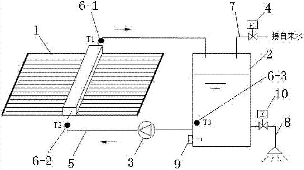
technical field [0001] The invention relates to a solar heat utilization technology, in particular, a method for judging water leakage of a fried pipe of a solar water heating system is designed. Background technique [0002] Solar water heating systems generally consist of solar collectors or collector arrays (hereinafter referred to as collectors), water tanks, pumps, solenoid valves, pipelines and controllers. [0003] like figure 1 As shown, it is a relatively typical system. The heat collector 1 absorbs sunlight and converts it into heat energy, and heats the water in the heat collector. When the water temperature T1 at the top of the heat collector 1 rises to the temperature difference with the water temperature T3 in the water tank After the set temperature difference is reached (such as 7°C), the water pump 3 starts to pump the cold water in the water tank into the heat collector 1, push out the hot water in the heat collector 1, and return it to the water tank 2, a...

Claims


Application Information

Patent Timeline
IPC IPC(8): F24J2/00
CPCY02E10/40
Inventor 邹怀松张一宇唐轩赵宏伟
Owner 北京创意博能源科技有限公司
Learn More