High-speed rotor structure of centrifugal blower

A technology of centrifugal blower and high-speed rotor, which is applied in the direction of mechanical equipment, machine/engine, liquid fuel engine, etc. It can solve the problems of large vibration, low blower efficiency, and system stability, and achieve balanced load, simple structure, and high efficiency. Effect

Inactive Publication Date: 2012-10-17
WUXI GL TUBRO COMPRESSOR
View PDF13 Cites 10 Cited by
  • Summary
  • Abstract
  • Description
  • Claims
  • Application Information

AI Technical Summary

Problems solved by technology

When the impeller is large, the mass at one end is too large, which will make the center of gravity of the rotor system deviate from the two radial bearings, forming a cantilever structure, so that when the impeller rotates at high speed, it will generate greater vibration and reduce the system. Stability, at the same time, it is necessary to expand the gap between the impeller and the volute to prevent scratching, and the expansion of the gap will lead to a decrease in the efficiency of the blower

Method used


Image

  • High-speed rotor structure of centrifugal blower

Examples


Embodiment Construction

[0009] Below the present invention will be further described in conjunction with the embodiment in the accompanying drawing:

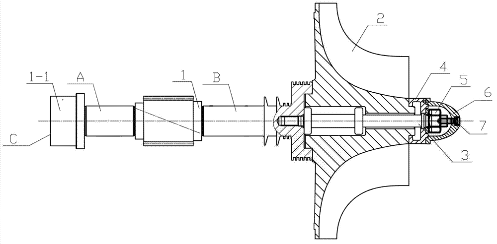
[0010] Such as figure 1 As shown, it includes high-speed gear shaft 1, impeller 2, tie rod bolt 3, C-shaped ring 4, nut 5, protective cover 6 and screw 7.

[0011] One end of the tie rod bolt 3 is connected to the high-speed gear shaft 1 , and then passed through the impeller 2 and the C-shaped ring 4 in sequence, and then the impeller 2 is fastened on the high-speed gear shaft 1 by tightening the nut 5 . The screw 7 is screwed into the threaded hole at one end of the tie rod bolt 3 , so that the protective cover 6 and the C-shaped ring 4 are connected. A and B of the high-speed gear shaft 1 are respectively in contact with radial bearings, and C is in contact with thrust bearings. The high-speed gear shaft 1 is a counterweight plate 1-1 structure between the radial bearing support A and the thrust bearing support C (on the high-speed gear shaft, and...


PUM


Abstract

The invention relates to a high-speed rotor structure of a centrifugal blower, which comprises a high-speed gear shaft, an impeller, a stay bolt, a C-shaped ring, a nut, a protection cover and a screw. One end of the stay bolt is connected with the high-speed gear shaft, and then sequentially penetrates through the impeller and the C-shaped ring, so as to fasten the impeller on the high-speed gear shaft by screwing the nut; the screw is screwed into a thread hole at one end of the stay bolt; and the protection cover is connected with the C-shaped ring. The high-speed gear shaft adopts a balancing disk structure between a bearing position of a radial bearing and a bearing position of a thrust bearing. The balancing disk is cylindrical and provided with a positioning shaft shoulder, and is homocentric with the high-speed gear shaft. The high-speed rotor structure is simple, the balancing disk structure at one end of a shaft is beneficial to the balancing of the center of gravity, the vibration amplitude of the impeller is reduced, the system stability is improved, the load of two radial bearings is effectively balanced, and a gap between the impeller and a spiral casing is reduced, so that the efficiency of the blower is improved.

Description

technical field [0001] The invention relates to a high-speed rotor structure of a centrifugal blower, in particular to an improved high-speed gear shaft structure of a single-stage high-speed centrifugal blower, belonging to the technical field of mechanical structures. Background technique [0002] At present, in the single-stage high-speed centrifugal blower used in the sewage treatment aeration system, the impeller obtains a higher speed through a gear speed increasing device. The motor is connected to the low-speed shaft, and the impeller is connected to the high-speed shaft. In the prior art, one end of the high-speed gear shaft is connected to the impeller, and after passing through a labyrinth-type sealing structure, it is supported by radial bearings. The other end is also supported by a radial bearing, and the end is in contact with a thrust bearing, and the two bearings are next to each other. When the impeller is large, the mass at one end is too large, which wi...

Claims


Application Information

Patent Timeline
Patent Type & Authority Applications(China)
IPC IPC(8): F04D29/28
Inventor 金华明
Owner WUXI GL TUBRO COMPRESSOR
Why Eureka
Try Eureka