
Oil cooling motor

An engine and oil cooling technology, applied in the cooling of engine components, machines/engines, engines, etc., can solve the problems of heating, spark plug hole cooling can not be improved, etc., to achieve heat suppression, cooling performance improvement, and improve cooling performance Effect

Active Publication Date: 2014-12-31
HONDA MOTOR CO LTD
View PDF5 Cites 0 Cited by
  • Summary
  • Abstract
  • Description
  • Claims
  • Application Information

AI Technical Summary

Problems solved by technology

Therefore, the cooling oil passage around the spark plug provided in the cylinder head around the spark plug hole is also arranged at a position corresponding to the central portion of the combustion chamber, and the oil passage for supplying cooling oil to the cooling oil passage around the spark plug faces toward the combustion chamber. It is formed in the cylinder head for a long distance, and the cooling oil may become hot during the circulation of the oil passage, so that the cooling performance around the spark plug hole may not be improved.

Method used


Image

  • Oil cooling motor
  • Oil cooling motor
  • Oil cooling motor

Examples


Embodiment Construction

[0088] Embodiments of the present invention will be described with reference to the drawings.

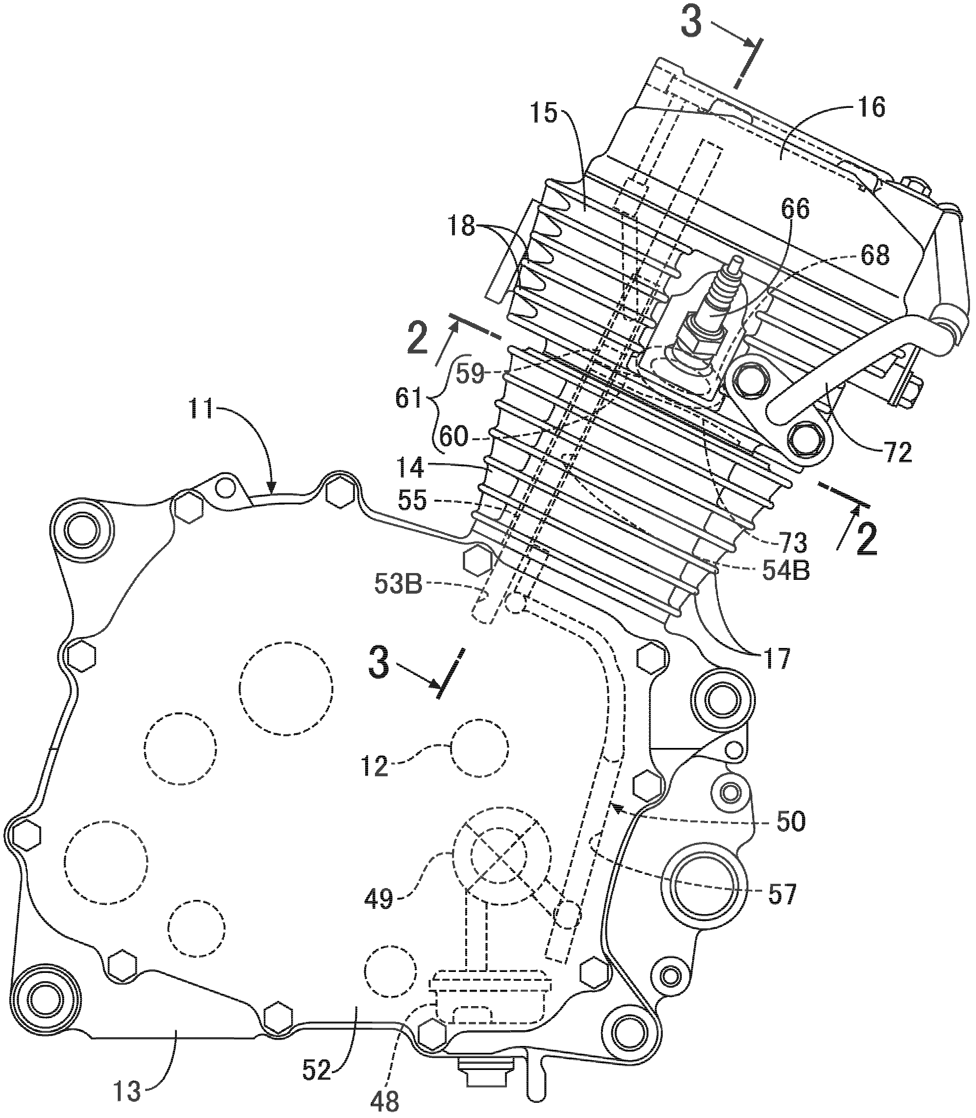
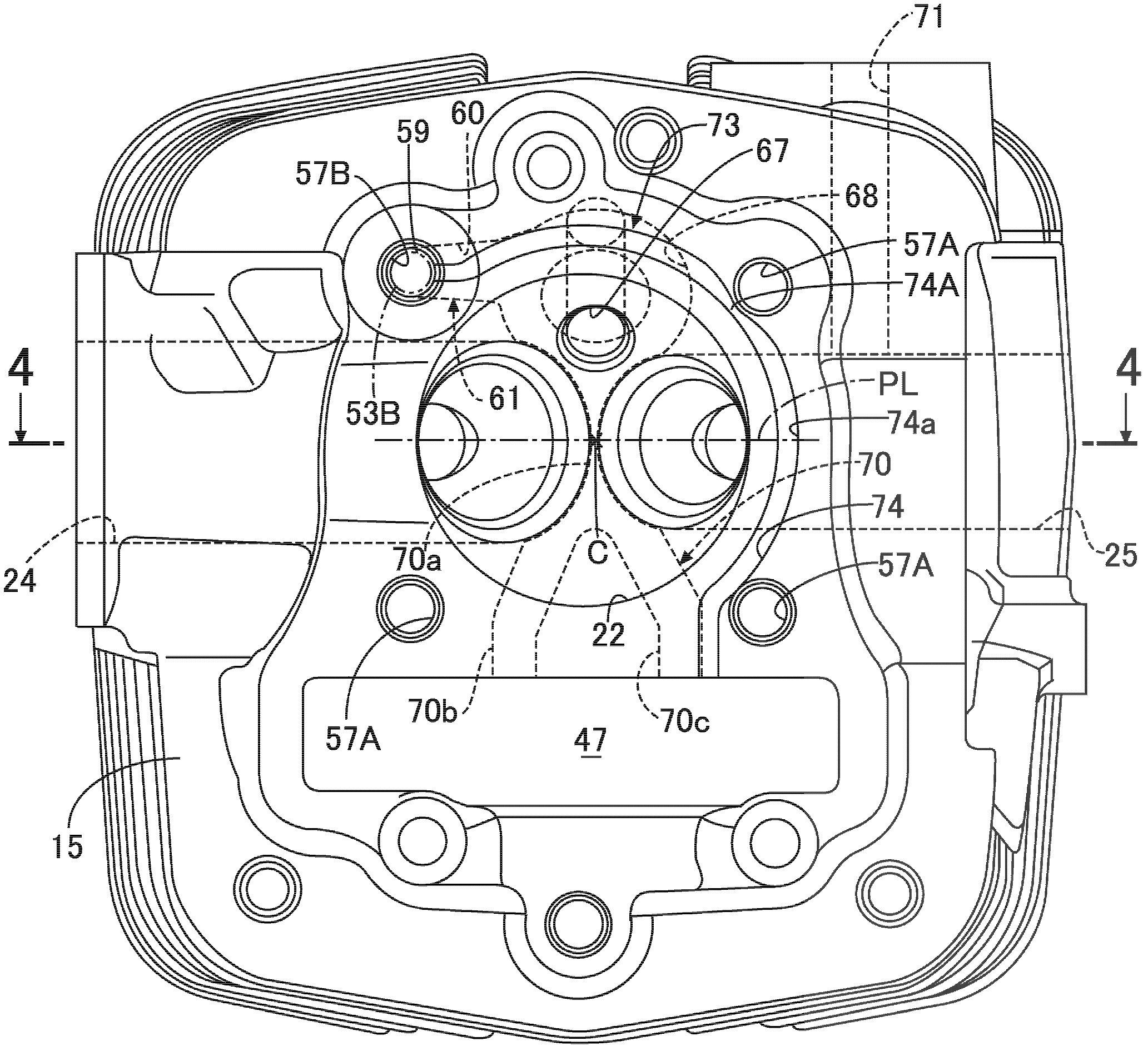
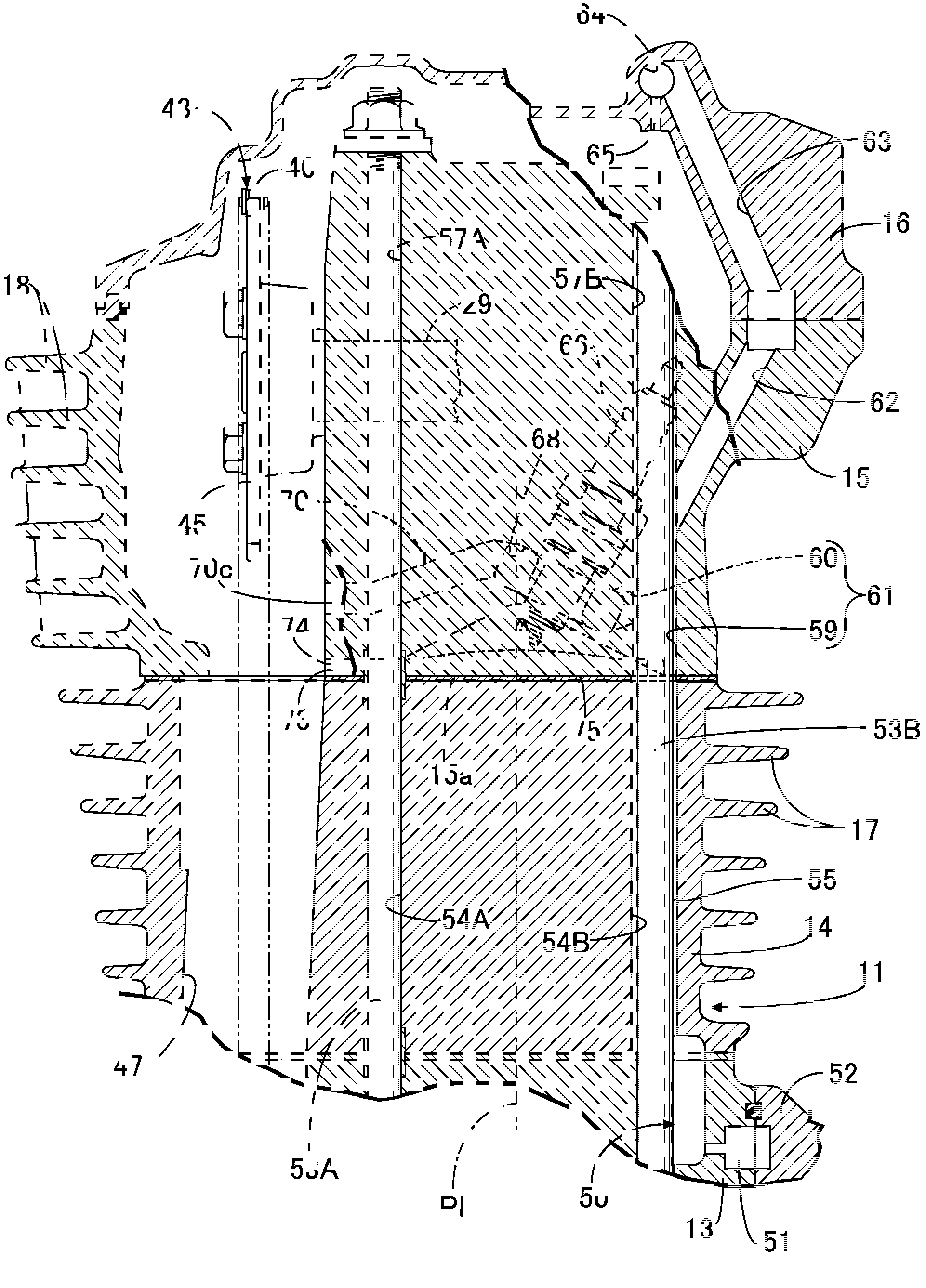
[0089] refer to Figure 1 to Figure 6 , to describe the first embodiment of the present invention, first, in figure 1 Among them, for example, the engine main body 11 of an oil-cooled engine mounted on a motorcycle includes a crankcase 13 that supports the crankshaft 12 in a rotatable manner. 13, the cylinder block 14 combined with the cylinder block 14, the cylinder head cover 16 combined with the cylinder head 15, and the outer surfaces of the cylinder block 14 and the cylinder head 15 are protrudingly provided with along A plurality of cooling fins 17 , 17 . . . ; 18 , 18 . . . arranged at intervals in the vertical direction.

[0090] together with reference Figure 2 to Figure 5 A slidable piston 20 is fitted into the cylinder tube 19 provided in the cylinder block 14 , and the piston 20 is connected to the crankshaft 12 via a connecting rod 21 . Between the cylinder block 14...


PUM


Abstract

The invention provides an oil cooling motor. A motor body is provided with a cooling oil circulation path which can circulate the cooling oil. A cooling oil passage which is a part of the cooling oil circulation path is arranged on a cylinder cover by surrounding a hole of a sparking plug. In the oil cooling motor, the cooling oil which is supplied to the cooling oil passage around the sparking plug is not easy to become hot, so the cooling performance around the hole of the sparking plug is improved. The hole (67) of the sparking plug is arranged on a projection image of the plane projection which is orthogonal to an axial line (C) of a cylinder barrel and on one side of a plane (PL). The plane includes a linear line which connects the centers of opening parts of a gas inlet (24) and a gas outlet (25), and the opening parts are open to a combustion chamber (22). A cooling oil supplying passage (61) is arranged on one side of the plane and is arranged on the cylinder cover (15), and is closer to the gas outlet than the gas inlet. The cooling oil supplying passage forms a part of the cooling oil circulation path and is connected with an upstream end of the cooling oil passage around the sparking plug.

Description

technical field [0001] The present invention relates to an oil-cooled engine, in which a cooling oil circulation passage for circulating cooling oil is provided in the engine main body, the engine main body includes a crankcase, a cylinder block, and a cylinder head, the crankcase supports the crankshaft in a rotatable manner, and the cylinder block It has a cylinder barrel and is combined with the crankcase. The cylinder barrel is fitted with the piston connected to the crankshaft and allows the piston to slide freely. The cylinder head is formed between it and the cylinder block and faces the piston. The combustion chamber at the top is combined with the cylinder block, and the cylinder head is provided with a spark plug hole, an air intake port and an exhaust port for arranging the spark plug, and the cooling oil passage around the spark plug forming a part of the cooling oil circulation path is used to surround The spark plug hole is arranged in the cylinder head. Backgr...

Claims


Application Information

Patent Timeline
Patent Type & Authority Patents(China)
IPC IPC(8): F01P3/02F01M1/06
Inventor 后闲祥次山元胜治梶原咏介菊池一纪
Owner HONDA MOTOR CO LTD
Learn More