
Tail gas-driven turbine generating set for internal combustion engine

A technology of turbine power generation and internal combustion engine, which is applied in the direction of circuit devices, exhaust devices, battery circuit devices, etc., and can solve the problems of energy loss and poor use of exhaust gas, etc.

Inactive Publication Date: 2012-10-17
北京百恒达石油技术有限公司
View PDF6 Cites 3 Cited by
  • Summary
  • Abstract
  • Description
  • Claims
  • Application Information

AI Technical Summary

Problems solved by technology

[0002] At present, the energy of the exhaust gas of an internal combustion engine accounts for about 30% of the thermal efficiency of the engine. The energy contained in the exhaust gas includes thermal energy and kinetic energy. For example, the exhaust gas of a car with a displacement of 1.4 liters can output about 9.8 kilowatts of energy at a high speed, and the speed of the turbine reaches 100,000. The rotation speed of some large-displacement turbines can be as high as 300,000 revolutions per minute, and the energy of the exhaust gas can reach 50 kilowatts or even higher. The turbine can convert 75% of the energy of the exhaust gas into kinetic energy, and the engine can convert the kinetic energy About 75% of the output is converted into electrical energy. In this case, if the output is 12 volts DC, a current of about 100 amperes can be obtained. This current is completely related to the displacement of the engine. The higher the current, the greater the current, but the existing technology does not make good use of the exhaust gas, resulting in energy loss, and it is difficult to achieve the purpose of energy saving and emission reduction to improve the thermal efficiency of the internal combustion engine

Method used


Image

  • Tail gas-driven turbine generating set for internal combustion engine

Examples


Embodiment Construction

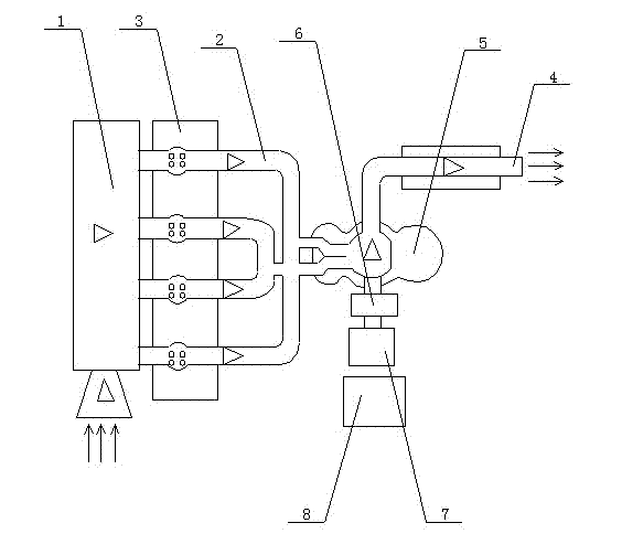
[0011] refer to figure 1 , The specific embodiment adopts the following technical scheme: it includes a turbine 5 and an air passage part 2, a turbine speed regulating mechanism part 6 and an engine part 3.

[0012] Described turbine 5 and gas passage part 2 mainly comprise the cavity that turbine 5, turbine shaft, exhaust gas inlet 1 and exhaust gas outlet 4 form, and the diameter of exhaust gas inlet 1 is less than the diameter of exhaust gas outlet 4, and by high-pressure exhaust gas inlet like this 1 is blown in to drive the turbine 5 to rotate, and then the pressure of the exhaust gas is reduced and the exhaust gas is discharged from the exhaust outlet 4. After this process, the turbine 5 drives the turbine shaft to make a circular motion, so that the turbine shaft drives the turbine 5 speed change mechanism to achieve the purpose of energy conversion.

[0013] The turbine speed regulating mechanism part 6 is converted into the speed range required by the rotor of the dri...


PUM


Abstract

The invention discloses a tail gas-driven turbine generating set for an internal combustion engine, which relates to the technical field of internal combustion engines. The tail gas-driven turbine generating set comprises a turbine (5), an air channel part (2), a turbine speed regulating mechanism part (6) and an engine part (3). The tail gas-driven turbine generating set can be used for supplying power to equipment such as automobiles, and can be used for driving an air conditioner of a vehicle body with electricity or supplying power to power storage equipment, so that the engine is not required to be used for driving an air conditioner compressor or driving a generator for charging a battery, power of an automobile is not consumed, the power output of the engine is ensured, tail gas is used for generating and supplying power, and the aims of saving energy, reducing emission and increasing the thermal efficiency of the internal combustion engine are fulfilled finally.

Description

technical field [0001] The invention relates to the technical field of internal combustion engines, in particular to an exhaust gas-driven turbine power generation device of an internal combustion engine. Background technique [0002] At present, the energy of the exhaust gas of an internal combustion engine accounts for about 30% of the thermal efficiency of the engine. The energy contained in the exhaust gas includes thermal energy and kinetic energy. For example, the exhaust gas of a car with a displacement of 1.4 liters can output about 9.8 kilowatts of energy at a high speed, and the speed of the turbine reaches 100,000. The speed of some large-displacement turbines can be as high as 300,000 revolutions per minute, and the energy of the exhaust gas can reach 50 kilowatts or even higher. The turbine can convert 75% of the energy of the exhaust gas into kinetic energy, and the engine can convert the kinetic energy About 75% of the output is converted into electrical ener...

Claims


Application Information

Patent Timeline
Patent Type & Authority Applications(China)
IPC IPC(8): F01N5/04F01D15/10H02J7/32
CPCY02T10/16Y02T10/12
Inventor 白云龙
Owner 北京百恒达石油技术有限公司
Learn More