
Roller-type hydraulic rocking arm component

A rocker arm assembly and roller-type technology, which is applied to the lubrication of engine components, valve accessories, and machines/engines. noise effect

Inactive Publication Date: 2012-10-17
东风朝阳朝柴动力有限公司
View PDF5 Cites 7 Cited by
  • Summary
  • Abstract
  • Description
  • Claims
  • Application Information

AI Technical Summary

Problems solved by technology

The camshaft, which is used as the engine valve mechanism, is currently placed downwards, and the power is transmitted to the rocker arm with tappets, push rods and other components. This structure is not only complicated, but also accelerates mechanical wear and increases the clearance. Therefore, frequent adjustments are required. Valve and rocker arm clearance to ensure work requirements

Method used


Image

  • Roller-type hydraulic rocking arm component
  • Roller-type hydraulic rocking arm component

Examples


Embodiment Construction

[0014] The principle and structure of the present invention will be further described below with reference to the accompanying drawings and through specific embodiments.

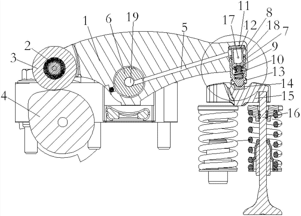
[0015] Roller type hydraulic rocker arm assembly, one end of the rocker arm 1 is provided with a short shaft, the short shaft is embedded with a bearing 2, the bearing is embedded in the roller 3, and the roller and the camshaft 4 form a transmission pair. The rocker arm is provided with an oil passage 5, and the middle part of the rocker arm is provided with a rocker shaft 6 (such as figure 1 ). The other end of the rocker arm is provided with a plunger sleeve 7, the plunger sleeve is sequentially equipped with a plunger 8, a check valve 9 and a return spring 10, the upper end of the plunger sleeve is provided with a plunger cover plate 11, and the plunger cover plate is provided with Oil return channel 12. The plunger sleeve is connected with the slide block 14 through the ferrule 13, the slide block is ...


PUM


Abstract

The invention discloses a roller-type hydraulic rocking arm component. The structure is as follows: one end of a rocking arm is provided with a short shaft, a bearing is embedded outside the short shaft and into the roller, and the roller and a camshaft form a transmission pair; an oil duct is arranged in the rocking arm, the middle part of the rocking arm is provided with a rocking arm shaft, the other end of the rocking arm is provided with a plunger bushing, and a plunger, a check valve and a return spring are sequentially arranged in the plunger bushing; the upper end of the plunger bushing is provided with a plunger cover plate, and the plunger cover plate is provided with an oil return channel; and the plunger bushing is connected with a slider through a cutting sleeve, the slider closely contacts a valve bridge, and the valve bridge contacts a valve push rod mechanism. The invention is suitable for an overhead camshaft mechanism, and the structure is simplified since the valve support column, the push rod and other parts connected with the cam are reduced. The rocking arm forms a zero-clearance fit with the camshaft and the valve push rod, thereby lowering the noise. On the premise of enhancing the strength of the engine block, cylinder head and the like, the volume of the engine is reduced, so that the structure is more compact reasonable, and the economical efficiency and power performance of the engine are enhanced.

Description

technical field [0001] The invention belongs to engine gas distribution system components, in particular to a roller type hydraulic rocker arm device. technical background [0002] With the rapid development of technology in the automotive industry and increasingly stringent environmental protection requirements, more stringent requirements are put forward for engines in terms of economy, emissions, and noise. At present, most engines use high-pressure common rail electronic injection technology, which makes the coordination requirements of fuel injection and valve timing more precise. The camshaft, which is used as the engine valve mechanism, is currently placed downwards, and the power is transmitted to the rocker arm with tappets, push rods and other components. This structure is not only complicated, but also accelerates mechanical wear and increases the clearance. Therefore, frequent adjustments are required. Valve and rocker arm clearance to ensure the work requiremen...

Claims


Application Information

Patent Timeline
Patent Type & Authority Applications(China)
IPC IPC(8): F01L1/12F01L1/18F01M9/10
Inventor 陈玉荣李晓刚张宏辉赵霄鹏张学存乌永波李长水张俊波蔡旭冰
Owner 东风朝阳朝柴动力有限公司
Learn More