
Fixing structure of motor shaft for electric vehicle

A technology for motor shafts and electric vehicles, which is applied to electric vehicles, motors, motor vehicles, etc., can solve the problems of weakening the tightening force of nuts that fasten motor shafts, and achieve the effect of easy position alignment and protection of wiring.

Active Publication Date: 2012-10-17
HONDA MOTOR CO LTD
View PDF6 Cites 9 Cited by
  • Summary
  • Abstract
  • Description
  • Claims
  • Application Information

AI Technical Summary

Problems solved by technology

[0003] However, in this method, the motor shaft and the swing arm are fastened by tightening the nut at the end of the motor shaft after inserting the motor shaft into the opening groove of the swing arm, so there is still a problem of weakening the fastening due to the driving reaction force of the motor. The possibility of the tightening force of the nut of the motor shaft, it is desirable to consider so that the motor shaft does not fall off the swing arm

Method used


Image

  • Fixing structure of motor shaft for electric vehicle
  • Fixing structure of motor shaft for electric vehicle
  • Fixing structure of motor shaft for electric vehicle

Examples


no. 1 approach

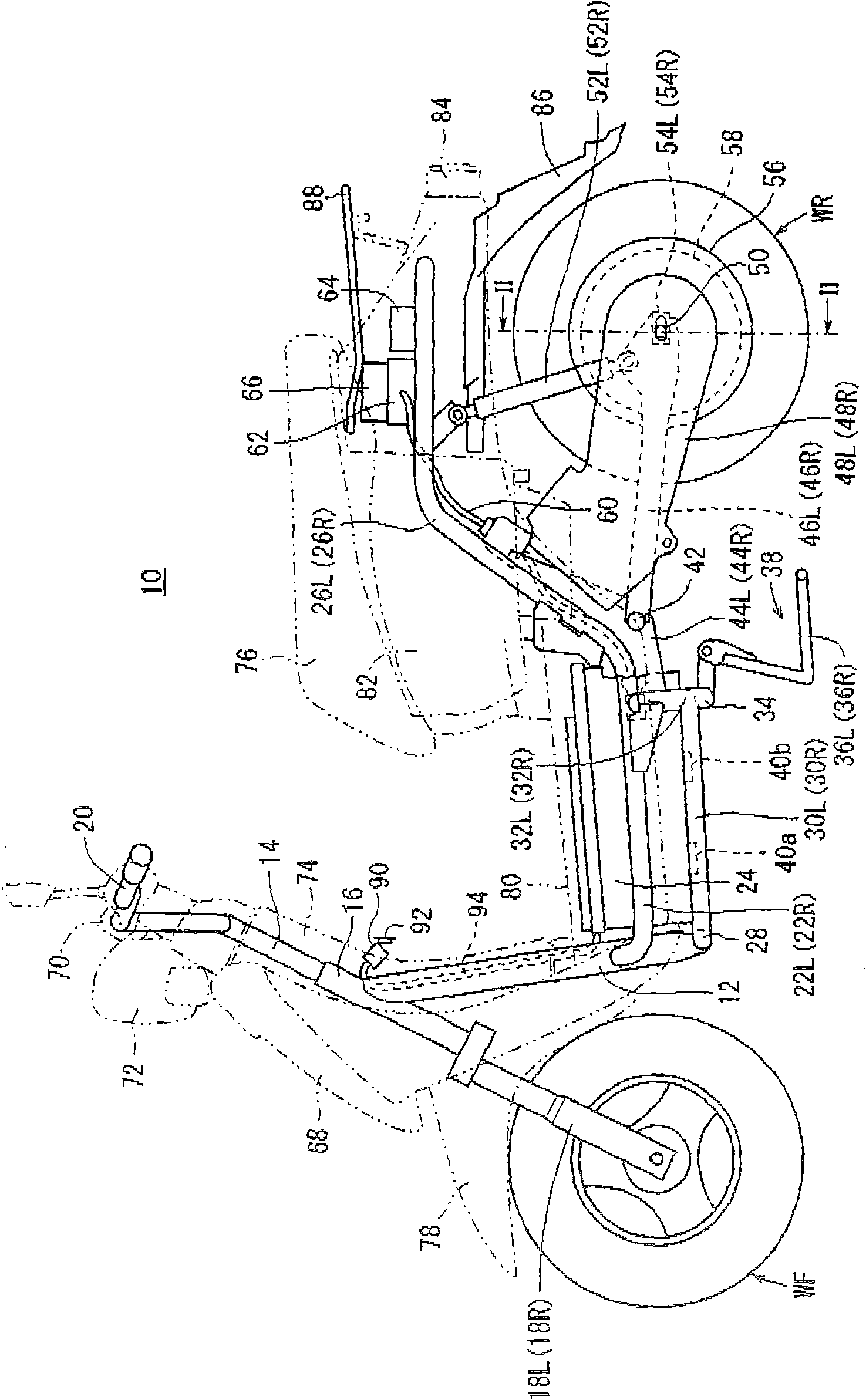
[0041] figure 1 It is a side view of an electric motorcycle (electric vehicle) 10 . It should be noted that, for the mechanisms or components provided on the left and right sides of the vehicle body, "L" is added to the reference symbols of the mechanisms or components on the left side, and "L" is added to the reference symbols of the mechanisms or components on the right side. R".

[0042] A head pipe 16 is coupled to an upper end portion of the main frame 12 of the electric motorcycle 10 , and the head pipe 16 pivotally supports the steering rod 14 so as to be rotatable. A pair of front forks 18L and 18R that rotatably support the front wheel WF are attached to the steering rod 14 , and the front wheel WF can be steered by a handle 20 attached to the upper portion of the steering rod 14 .

[0043] A pair of left and right upper frames 22L, 22R are connected to the lower portion of the main frame 12 , and the upper frames 22L, 22R extend obliquely downward from the connecti...

no. 2 approach

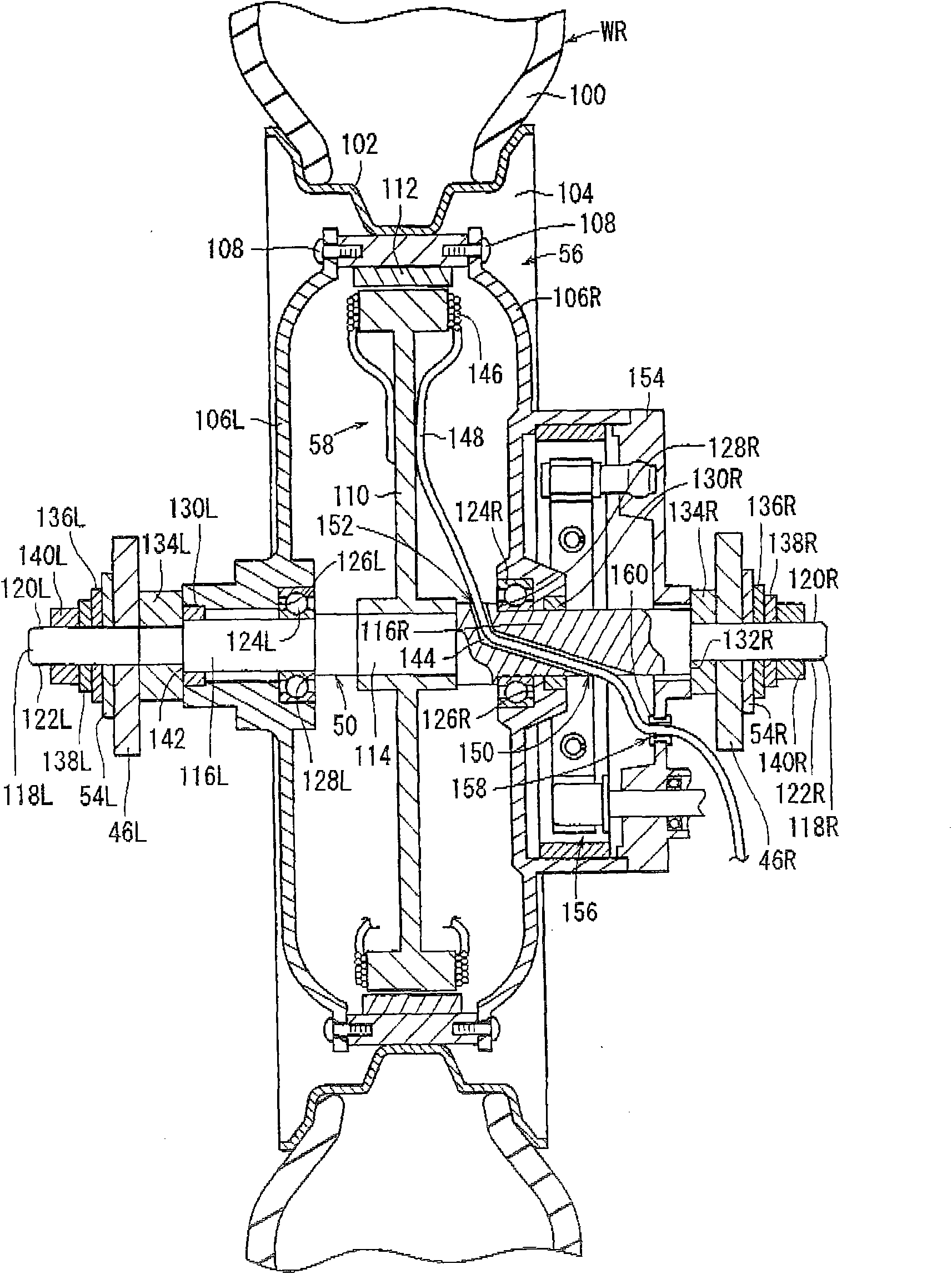
[0072] Next, a fixing structure of the motor shaft 50 for the electric motorcycle 10 will be described. Figure 5 yes means figure 1 The enlarged view of the main part of the shown swing arm 46L, Fig. 6 shows figure 1 A diagram of the stop mechanism 54L is shown. Figure 6A is the front view of the stop mechanism 54L, Figure 6B is the rear view of the stop mechanism 54L, Figure 6C It is a top view of the stopper mechanism 54L.

[0073] The fastening portion 118L of the motor shaft 50 is a portion for fastening to the vehicle body side with the nut 140L, and has an upper fastening surface 120L and a lower fastening surface 122L as described above. The fastening surfaces 120L, 122L are parallel to the front-rear direction of the vehicle body. The swing arm 46L has an arm portion 200 and an end peace portion 202. The end peace portion 202 is provided with an engaging opening 204 that matches the shape of the fastening portion 118L to restrict the rotation (rotation) of the...


PUM


Abstract

The invention provides a fixing structure of a motor shaft for an electric vehicle, and the motor shaft can be firmly fixed on the electric vehicle by the fixing structure. According to the fixing structure of the motor shaft (50) for the electric vehicle, fastening positions (118L, 118R) which are used for fastening the motor shaft on a side of the vehicle by using fixing components (140L, 140R) are provided at both ends of the motor shaft; a pair of fastening planes are formed on the fastening positions; support portions of the motor shaft are provided with a clamping opening (204) which is matched with a shape of the fastening positions, limits rotation of the motor shaft and opens towards a back of the vehicle; the fixing structure of the motor shaft for the electric vehicle has stopper mechanisms (54L, 54R) which are formed for preventing the fastening positions from disengaging from the clamping opening; the stopper mechanisms are arranged between the fixing components and the support portions of the motor shaft, and the stopper mechanisms comprise a through portion used for insertion of the fastening positions and a first clamping portion (212) clamped with a first embedded hole (210) which is arranged at the support portions of the motor shaft.

Description

technical field [0001] The present invention relates to a motor shaft fixing structure for an electric vehicle for fixing the motor shaft to a vehicle body. Background technique [0002] As a method of fixing the in-wheel motor to the swing arm, as shown in Japanese Patent Application Laid-Open No. 53-136736, it is described that a double-side chamfer (Japanese: 两面取り) processing part is provided at the end of the motor shaft and A method of setting corresponding opening slots to reliably fix and support the motor shaft against the rotational force of the motor shaft. [0003] However, in this method, the motor shaft and the swing arm are fastened by tightening the nut at the end of the motor shaft after inserting the motor shaft into the opening groove of the swing arm, so there is still a problem of weakening the fastening due to the driving reaction force of the motor. It is desirable to consider the possibility of the tightening force of the nut of the motor shaft so tha...

Claims


Application Information

Patent Timeline
Patent Type & Authority Applications(China)
IPC IPC(8): B60K7/00B62M7/12
CPCY02T10/641Y02T10/7005Y02T10/70B60K7/0007B60K17/24B60L50/50
Inventor 曹奇峰周越
Owner HONDA MOTOR CO LTD
Learn More