
Method for manifesting latent fingerprints on basis of electrochemical luminescence marker

A luminescent marker, electrochemical technology, applied in chemiluminescence/bioluminescence, analysis through chemical reaction of materials, medical science, etc., to achieve the effect of low self-quenching effect, high sensitivity and high luminous intensity

Active Publication Date: 2012-10-17
ZHEJIANG UNIV
View PDF5 Cites 14 Cited by
  • Summary
  • Abstract
  • Description
  • Claims
  • Application Information

AI Technical Summary

Problems solved by technology

Currently, there is no report on the use of activated terpyridine ruthenium complexes for fingerprinting and electrochemiluminescence imaging

Method used

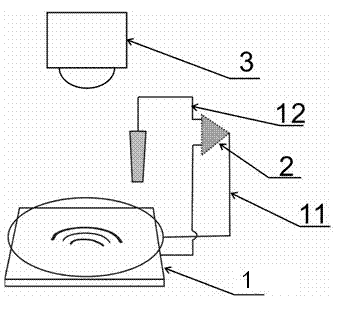
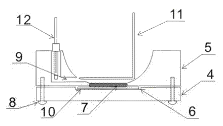

Image

  • Method for manifesting latent fingerprints on basis of electrochemical luminescence marker
  • Method for manifesting latent fingerprints on basis of electrochemical luminescence marker
  • Method for manifesting latent fingerprints on basis of electrochemical luminescence marker

Examples


Embodiment 1

[0039] (1) Press a oil submarine to seal on ITO;

[0040] (2) Incubate 4h with the activated triomin pyride complex, rinse with deodorized water to remove the unresponsive complex;

[0041] (3) Install the sample in the electrochemical reaction pool, add a 50mm di -borne ethanol phosphate buffer solution, apply a 1.3V potential through the triple electrode system, use a high -sensitive CCD camera to capture the image to obtain it to get the obtained image 3 The electrochemical emitting image shown.

Embodiment 2

[0043] (1) Press a oil submarine to seal on ITO;

[0044] (2) Incubate 6h with the activated triomin pyride complex, rinse with deodorized water to remove the unresponsive complex;

[0045] (3) Install the sample in the electrochemical reaction pool, add a 50mm di -borne ethanol phosphate buffer solution, apply a 1.3V potential through the triple electrode system, use a high -sensitive CCD camera to capture the image to obtain it to get the obtained Figure 4 The electrochemical emitting image shown.

Embodiment 3

[0047] (1) Press a oil submarine to seal on ITO;

[0048] (2) Then use the diluted triple pyridine pyride complex to incubate 3.5h, rinse with deodorized water to remove the unresponsive complex;

[0049] (3) Install the sample in the electrochemical reaction pool, add a 50mm di -borne ethanol phosphate buffer solution, apply a 1.3V potential through the triple electrode system, use a high -sensitive CCD camera to capture the image to obtain it to get the obtained Figure 5 The electrochemical emitting image shown.


PUM


Abstract

The invention discloses a method for manifesting latent fingerprints on the basis of an electrochemical luminescence marker. According to the method, an activated terpyridine ruthenium composite is used as the electrochemical luminescence marker; the activated terpyridine ruthenium composite can be subjected to covalent binding with an amino group in fingerprint amino acid through N-hydroxysuccinimide eater on a molecule, so that the terpyridine ruthenium composite is marked and fixed on the fingerprints; then the terpyridine ruthenium composite and a coreactant (namely dinormal-butyl ethanolamine) in a solution are subjected to electrochemical luminescence reaction under certain potential, so that lines of the fingerprints comprising the integral morphology (namely a primary structure) and detailed features (namely a secondary structure) are manifested; according to the adopted electrochemical luminescence technology, an excitation light source is not required to be added, back light is eliminated, a self-quenching phenomenon of a radiant agent is greatly avoided, and the method is obviously superior to the traditional fluorescence imaging method; and an image can be quickly acquired by an imaging technology, and the speed of acquiring the image by the imaging technology is far higher than the speed of acquiring the image by a scanning electrochemical microscopy; and the used electrochemical luminescence coreactant is dinormal-butyl ethanolamine, and has the characteristics of high luminous intensity and environment-friendliness.

Description

Technical field [0001] The present invention is a potential fingerprint display technology field, and specially involves a potential fingerprint display method based on electrochemical luminous symbols. Background technique [0002] The fingerprint is composed of a spine protruding series called friction, and has a very special physiological structure and characteristic system.Fingerprints play an important role in forensic identification and personal identification, and at the same time are widely used in safety inspection, access control, personal certification and other fields in daily life.The so -called potential fingerprint refers to when a person's finger and palm touch the object, due to the interaction of sweat and oil and the interaction of oil, the printed marks that refer to the mastoid line of the palm face (divided into sweatThe scallion line area and the depression line areas composed of dirt and oil).In most cases, it cannot be directly inspected by the eyesight o...

Claims


Application Information

Patent Timeline
Patent Type & Authority Applications(China)
IPC IPC(8): A61B5/117G01N21/76A61B5/1172
Inventor 许林茹李妍苏彬
Owner ZHEJIANG UNIV
Learn More