
Production system, in particular for free-form bending, having integrated workpiece and tool manipulator

A production equipment and bending technology, applied in the direction of forming tools, metal processing equipment, manufacturing tools, etc., can solve the problem that bending dies cannot use clamping jaws, etc., and achieve the effect of extensive operation and manipulation, and simplified manipulation.

Active Publication Date: 2012-10-03
TRUMPF MASCHEN AUSTRIA
View PDF9 Cites 21 Cited by
  • Summary
  • Abstract
  • Description
  • Claims
  • Application Information

AI Technical Summary

Problems solved by technology

Manipulation of bending dies in this configuration also cannot use the same jaws that are used for manipulation of sheet metal

Method used


Image

  • Production system, in particular for free-form bending, having integrated workpiece and tool manipulator
  • Production system, in particular for free-form bending, having integrated workpiece and tool manipulator
  • Production system, in particular for free-form bending, having integrated workpiece and tool manipulator

Examples


Embodiment Construction

[0027] First of all, it must be established that in the different described embodiments, the same parts are assigned the same reference symbols or the same component designations, wherein the disclosure content contained in the entire description can be transferred according to the meaning with the same reference symbols or the same On the same part of the component name. Positional indications selected in the description, such as for example top, bottom, side, etc., also refer to the direct description and the illustrated figures and can be switched to the new position in the event of a position change. Furthermore, individual features or combinations of features from the various exemplary embodiments shown and described can themselves be independent, inventive or solutions according to the invention.

[0028] All descriptions of numerical ranges in this specification should be understood as follows: the description includes any and all partial ranges therein, for example, de...


PUM


Abstract

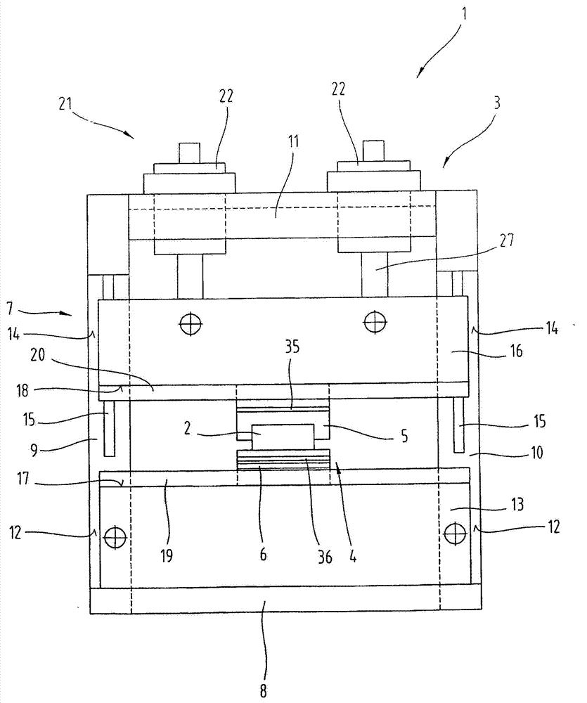
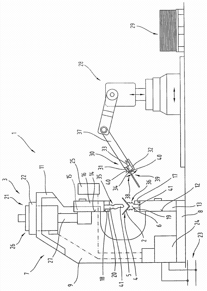
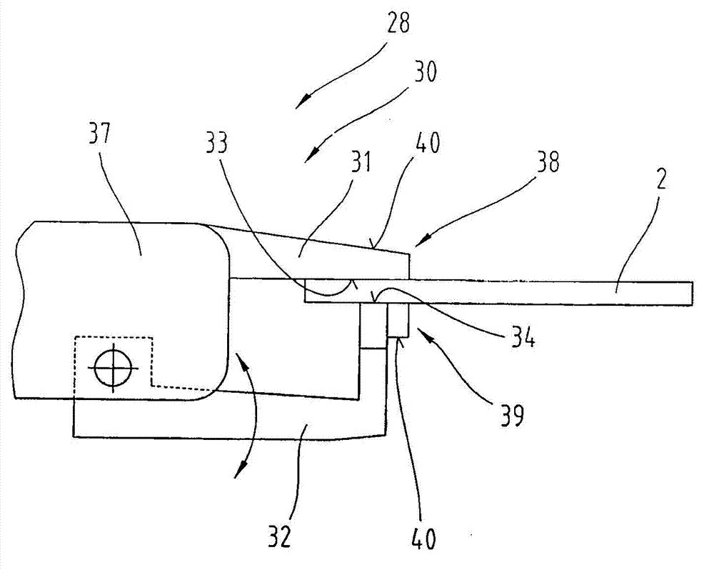
The invention relates to a production system (1) for free-form bending. The production system comprises a bending press (3) having bending tools (4), which are interchangeably retained in tool holders (19, 20), a manipulator (28) having gripping tongs (30), which have gripping fingers (31, 32) and a recess (35, 36) that is arranged in the bending tool (4) and that has stop areas (49, 50) spaced apart from each other for manipulating the bending tool (4). At the ends (38, 39) of the gripping fingers (31, 32), additional contact surfaces (40) are formed on sides of the gripping fingers (31, 32) facing away from each other. The ends (38, 39) of the gripping fingers (31, 32) are inserted into the recess (35, 36) in order to retain the bending tool (4). The contact surfaces (40) are pressed against the stop areas (49, 50) in the direction opposite from the clamping force for retaining the workpiece (2) to be produced.

Description

technical field [0001] The invention relates to a production plant as described in claim 1, in particular for free-form bending of workpieces to be produced from sheet metal. Background technique [0002] A die changing system for bending dies is known from EP 1 862 255 A1, in which a separate manipulator is provided for manipulating the bending dies. The manipulator has a pin-shaped projection which is inserted into a recess in the bending die itself for manipulation. For this purpose, specially designed actuating pins are required which are only used for actuating the bending tool. In addition, the clamping of the bending tool can be released during clamping of the bending tool in the tool holder either by means of the actuating pin or by means of an additional actuating pin. This can be done mechanically via an additional additional actuating pin, or also by the first actuating pin via actuation of pressure medium actuation. [0003] JP06-234018 describes another die c...

Claims


Application Information

Patent Timeline
Patent Type & Authority Applications(China)
IPC IPC(8): B21D5/02B21D37/04B21D43/00B25J15/00B23Q3/155B23Q7/04
CPCB21D43/00B21D5/0254B21D5/0209B21D5/02B21D37/04B21D37/14
Inventor T·登克迈尔
Owner TRUMPF MASCHEN AUSTRIA
Learn More