
Heat dissipation processing device and mobile terminal

A mobile terminal and processing device technology, applied in the field of mobile communication, can solve the problems of high price and difficult comprehensive effect, and achieve the effect of improving grounding performance and radio frequency signal receiving performance

Active Publication Date: 2012-10-03
ZTE CORP
View PDF3 Cites 17 Cited by
  • Summary
  • Abstract
  • Description
  • Claims
  • Application Information

AI Technical Summary

Problems solved by technology

However, these heat-conducting materials can only achieve the purpose of heat dissipation, and it is difficult to have other comprehensive effects, and due to raw materials, manufacturing processes and other reasons, the price is relatively expensive when used in a large area.

Method used

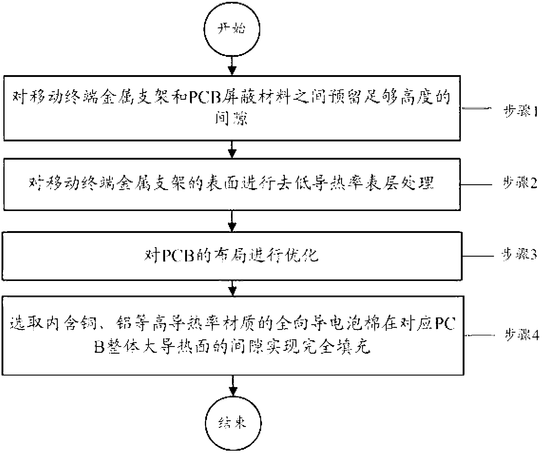

Image

  • Heat dissipation processing device and mobile terminal
  • Heat dissipation processing device and mobile terminal
  • Heat dissipation processing device and mobile terminal

Examples


Embodiment 1

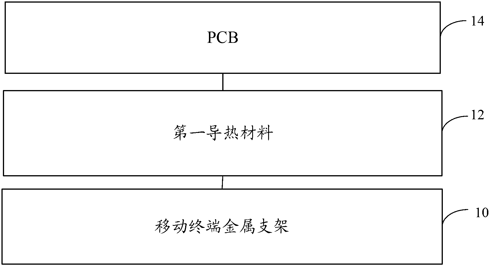
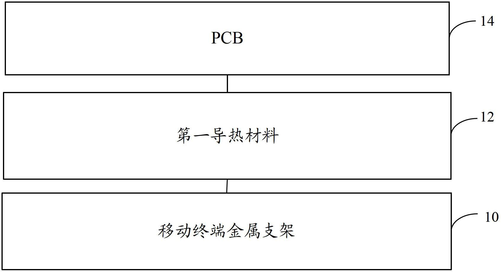
[0023] According to an embodiment of the present invention, a heat dissipation processing device is provided, figure 1 is a schematic diagram of a heat dissipation processing device according to an embodiment of the present invention, such as figure 1 As shown, the heat dissipation treatment device according to the embodiment of the present invention includes: the metal bracket 10 of the mobile terminal that has been treated to remove the low thermal conductivity surface layer, the first thermally conductive material 12 with a rough surface, and the PCB 14 with a multi-layer structure. The following describes the embodiment of the present invention Each module is described in detail.

[0024] Specifically, the mobile terminal metal bracket 10 is located between the mobile terminal LCD and the PCB 14, and a certain gap needs to be maintained between the mobile terminal metal bracket 10 and the PCB 14. In the embodiment of the present invention, the mobile terminal metal bracket...

Embodiment 2

[0054] According to an embodiment of the present invention, a mobile terminal is provided. The mobile terminal according to the embodiment of the present invention includes the heat dissipation processing device described in the first embodiment of the device. The embodiment of the present invention can be understood according to the description of the first embodiment of the device above. I won't repeat them here.

[0055] To sum up, with the help of the technical solution of the embodiment of the present invention, by filling the gap between the metal bracket of the mobile terminal and the PCB with the low thermal conductivity surface treatment in the past, a conductive heat-conducting material can be used to effectively dissipate heat in the electronic system of the mobile terminal. While processing, it can improve the grounding performance of the electronic system and the receiving performance of radio frequency signals.


PUM


Abstract

The invention discloses a heat dissipation processing device and a mobile terminal. The device comprises a mobile terminal metal stand subjected to low-thermal-conductivity surface removal treatment, a first heat conducting material with rough surface, and a PCB (printed circuit board) with a multilayer structure, wherein the mobile terminal metal stand is located between a mobile terminal LCD (liquid crystal display) and the PCB; the space between the mobile terminal metal stand and the PCB is filled with the first heat conducting material; large-power devices on the PCB are arranged at a middle position of the device surface of the PCB, and are kept with gap between the devices; at least one layer of ground copper is arranged in the PCB; ground copper is arranged on the bottom or other positions of the large-power devices on the device surface of the PCB; and a ground hole is formed on the device surface of the PCB. Based on the technical scheme provided by the invention, the heat dissipation processing device provided by the invention can improve the overall electromagnetic compatibility index, radio frequency index and structural reliability index while the mobile terminal electronic system is subjected to the effective heat dissipation treatment.

Description

technical field [0001] The invention relates to the field of mobile communication, in particular to a heat dissipation treatment device and a mobile terminal. Background technique [0002] In the prior art, a mobile terminal is especially an intelligent terminal based on the third-generation mobile communication technology (3rd-generation, referred to as 3G) and the long-term evolution (Long Term Evolution, referred to as LTE) system. The frequency is getting higher and higher, the memory access speed is getting faster and faster, and the power consumption of RF power amplifier and power management is also getting higher and higher. Therefore, the heat dissipation treatment (also called thermal design) of mobile terminals is particularly important. [0003] Thinner appearance and more complex functions are the two sides of a smart mobile terminal. On the one hand, it has a cool body and colorful applications; In the era of development, thermal design is very important. [...

Claims


Application Information

Patent Timeline
Patent Type & Authority Applications(China)
IPC IPC(8): H05K7/20H05K9/00
Inventor 张永亮
Owner ZTE CORP
Learn More