
antenna

An antenna and microstrip line technology, applied in the field of chip antennas, can solve the problems of antenna signal interference, inability to place electronic components, waste of space, etc., and achieve the effect of utilizing space

Inactive Publication Date: 2015-09-30
AAC ACOUSTIC TECH (SHENZHEN) CO LTD +1
View PDF5 Cites 0 Cited by
  • Summary
  • Abstract
  • Description
  • Claims
  • Application Information

AI Technical Summary

Problems solved by technology

[0004] The antenna related to the present invention includes an antenna module and a microstrip line attached to the inner surface of the mobile phone casing. Since the antenna module is directly attached to the inner surface of the mobile phone casing, no other electronic components can be placed near the antenna module. , so as not to cause the signal of the antenna to be interfered, which causes a lot of waste of space

Method used


Image

  • antenna
  • antenna
  • antenna

Examples


Embodiment Construction

[0026] The present invention will be further described below in conjunction with the accompanying drawings and embodiments.

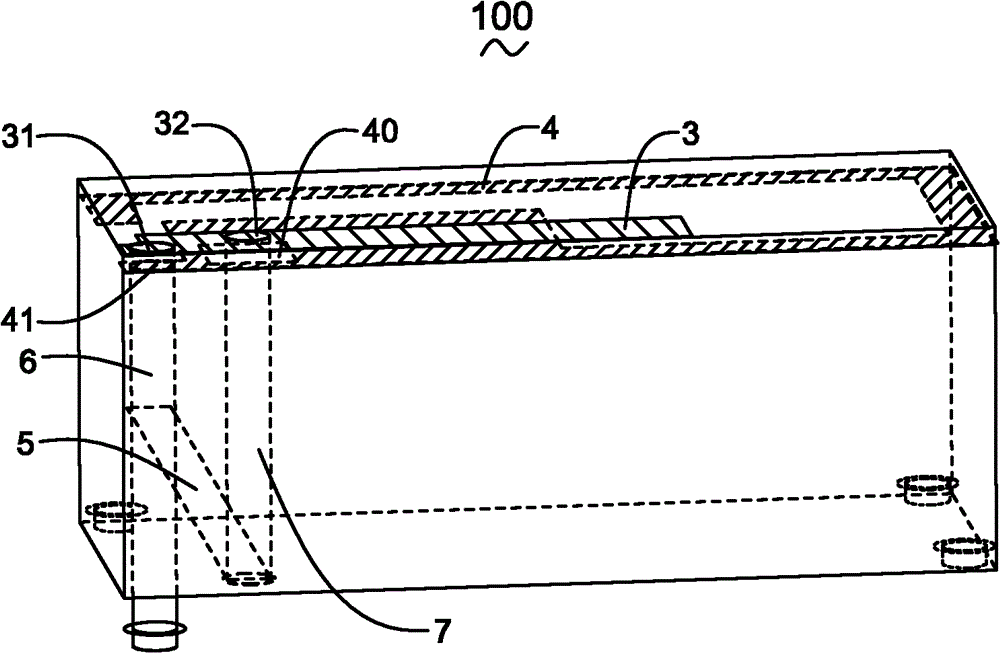
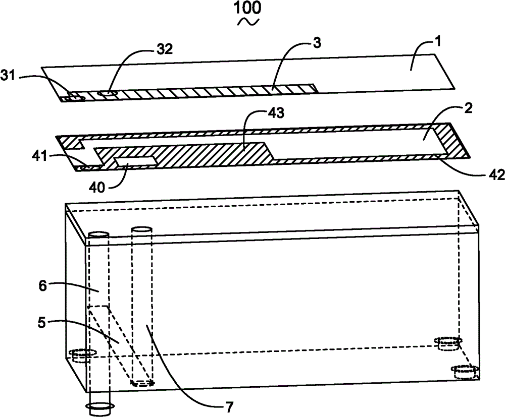
[0027] It should be noted that, in figure 2 , image 3 , Figure 4 , Figure 7 , Figure 9 In , in order to see the positional relationship between the coupling portion 3 and the radiation portion 4 more clearly, hatching lines are added between the coupling portion 3 and the radiation portion 4 .

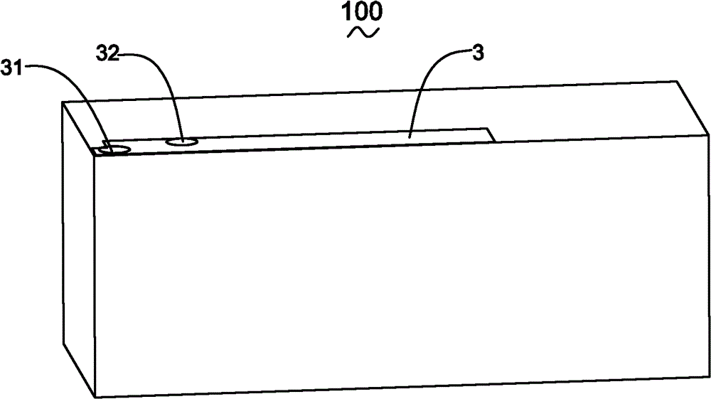
[0028] Such as Figure 1 to Figure 4 Shown is the antenna 100 of the present invention, which includes the microstrip line 5 extending to the outside of the antenna 100, the first dielectric layer 1 and the second dielectric layer 2 stacked together, and the upper surface of the first dielectric layer 1 The coupling part 3, the radiation part 4 provided on the upper surface of the second dielectric layer 2, and the first conduction channel 7 and the second conduction channel 6 electrically penetrating through the first dielectric layer 1 and the second...


PUM


Abstract

The invention provides an antenna composed of a microstrip line, a first medium layer, a second medium layer, a coupling portion, a radiation portion, a first communicating channel and a second connecting channel. The microstrip line extends outwards, the first medium layer and the second medium layer are stacked together, the coupling portion is arranged on the upper surface of the first medium layer, the radiation portion is arranged on the upper surface of the second medium layer, the first connecting channel is electrically communicated with the first medium layer, the second connecting channel is electrically communicated with the second medium layer, the coupling portion is provided with a feed-in point and a first grounding point which has a certain distance with the feed-in point, the radiation portion is provided with a second grounding point, one end of the first connecting channel is electrically connected with the feed-in point of the coupling portion, the other end of the first connecting channel is electrically connected with the microstrip line, and the second connecting channel is electrically connected the first grounding point and the second grounding point to an outside grounding portion. The antenna can make full use of space inside a product.

Description

【Technical field】 [0001] The present invention relates to an antenna, in particular to a chip antenna. 【Background technique】 [0002] With the rapid development of modern electronic communication technology, the requirements for various electronic communication equipment are getting higher and higher, especially in mobile communication, such as mobile phones, PDAs, etc. Moving towards the goal of being light, thin, short, and small, in order to meet higher-quality consumer demand. [0003] As far as the mobile phone is concerned, the most important part of its design is the antenna design, because the quality of the antenna design directly determines the quality, shape, size and other important factors of the electronic communication equipment. Generally, common antennas can be roughly divided into two types: external antennas and internal antennas: external antennas include monopole antennas and helix antennas, etc.; internal antennas include planar inverted-F antennas ( ...

Claims


Application Information

Patent Timeline
Patent Type & Authority Patents(China)
IPC IPC(8): H01Q1/48H01Q1/50H01Q1/52
Inventor 黄源烽戴有祥
Owner AAC ACOUSTIC TECH (SHENZHEN) CO LTD
Learn More