
Broadband dual-polarized omnidirectional ceiling antenna

A ceiling antenna and vertically polarized antenna technology, which is applied to antenna unit combinations with different polarization directions, antenna coupling, antenna grounding devices, etc. Can not achieve the effect and other problems, to achieve the effect of improving spectrum utilization, low cost and small size

Inactive Publication Date: 2012-10-03
COMBA TELECOM SYST CHINA LTD +1
View PDF6 Cites 40 Cited by
  • Summary
  • Abstract
  • Description
  • Claims
  • Application Information

AI Technical Summary

Problems solved by technology

Although the technical solution claims that it has achieved a relatively good technical effect, the experiment conducted by the applicant using the technical solution shows that the technical solution cannot achieve the claimed effect. Therefore, it is doubtful whether the technical solution is feasible
The applicant believes that the upper conical vibrator and the lower conical vibrator are aligned and connected, and the magnetic field formed at the alignment position of the two is the strongest, and the horizontally polarized antenna is set at this position, which will affect the standing of the vertically polarized antenna. The wave brings a great degree of interference, and also makes the ceiling antenna unable to be miniaturized
Moreover, the ceiling antenna should pursue the overall technical effect, but for the situation where vertically polarized antennas and horizontally polarized antennas are installed in the ceiling antenna at the same time, this technical solution does not consider solving the problem of high isolation caused by it

Method used


Image

  • Broadband dual-polarized omnidirectional ceiling antenna
  • Broadband dual-polarized omnidirectional ceiling antenna
  • Broadband dual-polarized omnidirectional ceiling antenna

Examples


Embodiment Construction

[0033] Below in conjunction with accompanying drawing and embodiment the present invention will be further described:

[0034] The main purpose of the present invention is to improve the spectrum utilization rate of the wireless communication system, to improve the data transmission capability of the system as much as possible without increasing the spectrum resources, to achieve good signal coverage through polarization diversity, and to be compatible with 2G, 3G and TD-LTE and other mobile communication systems can not only replace the ceiling antenna in the existing network, but also innovatively solve the problem of shared antenna between TD-LTE and the existing room, and integrate with the existing GSM / TD-SCDMA through multi-band The system is combined, and MIMO is realized in a pair of physical antennas through dual-polarized oscillators, which significantly reduces the engineering cost of TD-LTE room division construction and transformation.

[0035] The technical solut...


PUM


Abstract

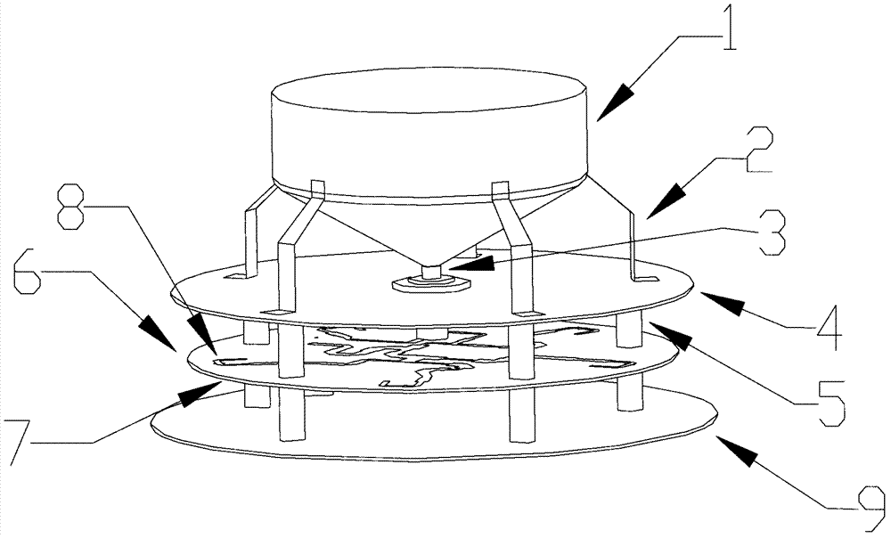
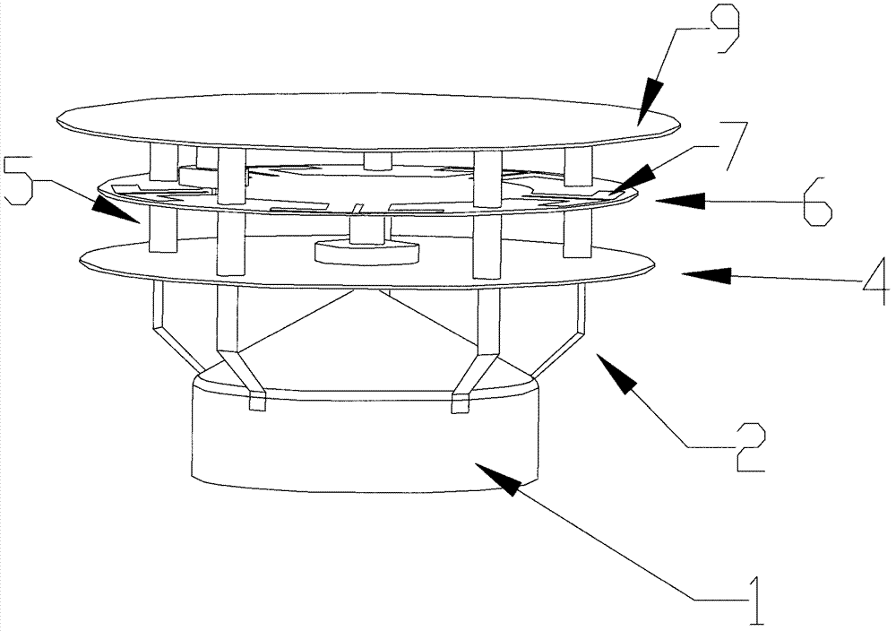
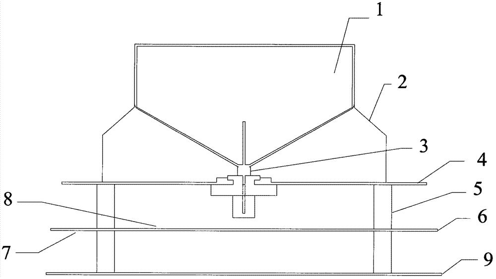
The invention discloses a broadband dual-polarized omnidirectional ceiling antenna, which comprises a round bottom plate, an antenna cover, a vertically-polarized antenna and a horizontally-polarized antenna, wherein the bottom plate and the antenna cover are assembled to cover the vertically-polarized antenna and the horizontally-polarized antenna; the vertically-polarized antenna comprises a round vertically-polarized metal plate provided with a through hole at the middle part, a metal support seat fixed in the through hole and having a lead hole, and a radiation oscillator vertically arranged on the metal support seat; the horizontally-polarized antenna is arranged on a round horizontally-polarized dielectric plate; the horizontally-polarized dielectric plate is above the bottom plate; and the vertically-polarized metal plate is above the horizontally-polarized dielectric plate, and a plurality of supporting columns pass through the horizontal dielectric plate and respectively fix and support the vertically-polarized metal plate and the bottom plate. The antenna manufactured according to the invention has strong environment applicability, low standing-wave ratio, high isolation degree, excellent antenna performance and a simple and compact structure.

Description

【Technical field】 [0001] The invention relates to mobile communication coverage technology, especially MIMO (Multiple Input Multiple Output) related technology of mobile communication indoor distribution system, and specifically relates to a broadband dual-polarized omnidirectional ceiling antenna. 【Background technique】 [0002] The indoor distribution system is an important part of today's wireless communication system, and the performance of the indoor distribution antenna directly affects the overall performance of the system. With the rapid development of mobile communication systems, the complexity of the system is getting higher and higher, which also puts forward new requirements and challenges for the performance of the antenna. Moreover, as users' awareness of protection against antenna radiation increases, stricter requirements are placed on the size of the indoor distribution system. Therefore, designing and adopting a new type of miniaturized and high-performan...

Claims


Application Information

Patent Timeline
IPC IPC(8): H01Q1/36H01Q1/48H01Q1/52H01Q21/24H01R9/05
Inventor 刘培涛刘聪孙善球钟锦庆吴荣广吴宝庭吴兵林巧新刘少聪许时彰
Owner COMBA TELECOM SYST CHINA LTD
Learn More