Liquid injection device for lithium ion battery
A lithium-ion battery and liquid injection device technology, which is applied to battery components, circuits, electrical components, etc., can solve problems such as increased equipment investment, reduced production efficiency, and increased battery production costs
- Summary
- Abstract
- Description
- Claims
- Application Information
AI Technical Summary
Problems solved by technology
Method used
Image
Examples
Embodiment 1
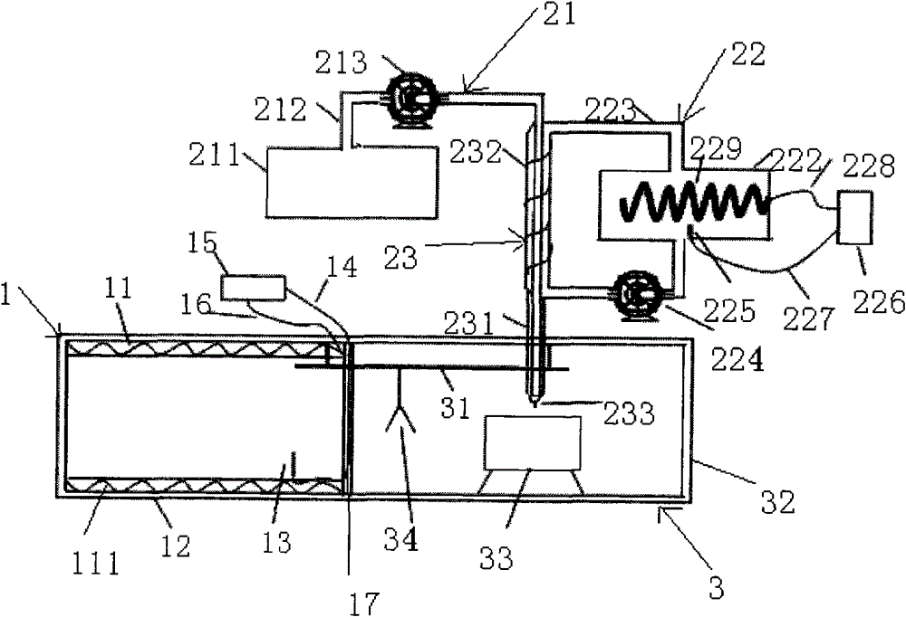
[0027] like figure 1 As shown, a lithium-ion battery liquid injection device includes a liquid injection system 3, a cell preheating system 1 and / or an electrolyte heating system 2, and the cell preheating system 1 is the upper station of the liquid injection system 3 And there is a battery outlet between the two
[0028] 17. The electrolyte heating system 2 is located above the liquid injection system 3.
[0029] The battery preheating system 1 includes a battery heat supply system 11, a battery heat preservation chamber 12 and a temperature control circuit for controlling the temperature in the battery heat preservation chamber 12, and the battery heat supply system 11 is set in the The resistance wire 111 inside the cell insulation cavity 12 is described.
[0030] The temperature control loop includes a first temperature-sensing probe 13 arranged inside the cell insulation chamber 12, a first temperature-regulating controller 15, and a first temperature-sensing probe 13 f...
Embodiment 2
[0039] The structure of the electrolyte heating system 2 of this embodiment is different from that of Embodiment 1. This embodiment uses a resistance wire direct heating system, and the rest is the same as that of Embodiment 1, and will not be repeated here.
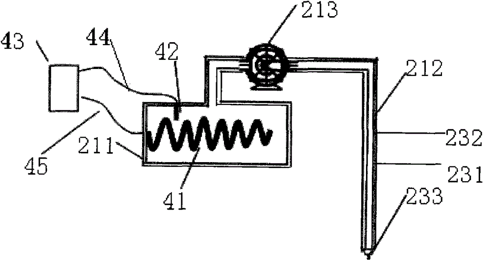
[0040] refer to figure 2 , the resistance wire heating system includes a resistance wire 41 arranged in the electrolyte storage tank 211, a third temperature-sensing probe 42 arranged in the electrolyte storage tank 211, a third temperature probe 42 arranged outside the electrolyte storage tank 211 A temperature adjustment controller 43, a third temperature sensing line 44 for connecting the third temperature sensing probe 42 and the third temperature adjustment controller 43, the third temperature adjustment controller 43 passes through the third resistance wire wire 45 is connected with the electrolyte storage tank 211.
[0041] When working, turn on the power supply, the resistance wire 41 starts to work, and the el...
Embodiment 3
[0044] The structure of the electrolyte heating system 2 is different from that of the embodiment 1, and the cells are not heated. This embodiment uses an infrared heating system, and the rest is the same as that of the embodiment 1, which will not be repeated here.
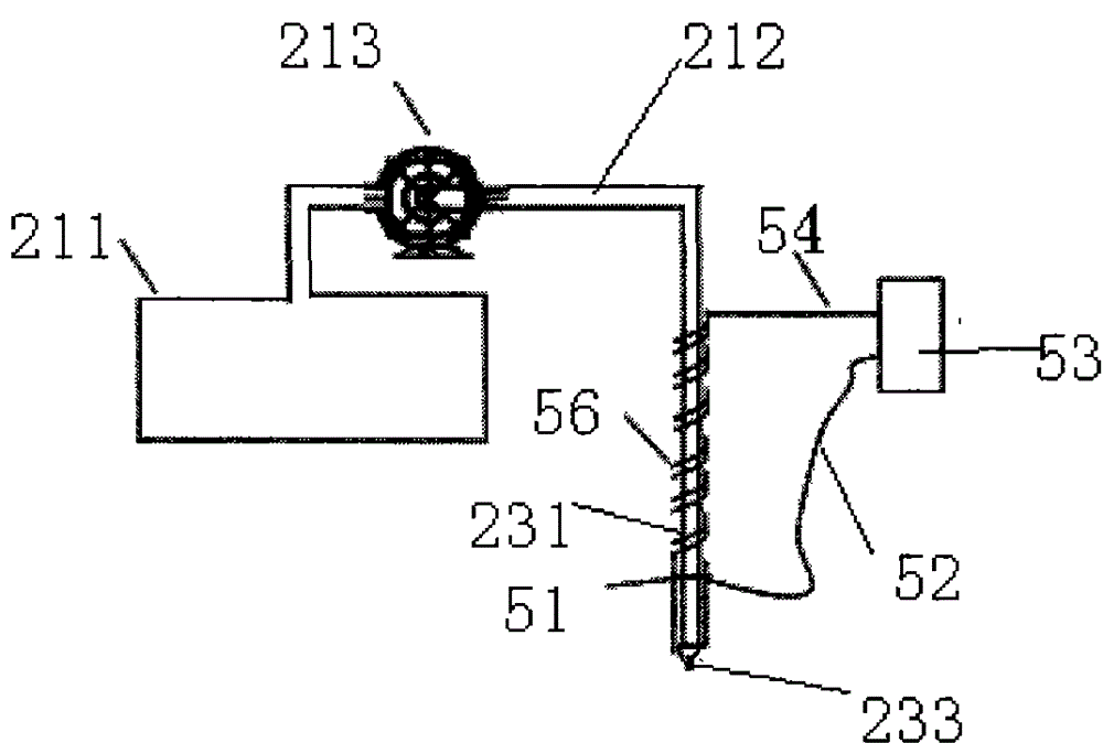
[0045] refer to image 3 , the infrared heating system includes an infrared heating tube 56 sleeved outside the heat exchanger 231, a fourth temperature-sensing probe 51 arranged outside the catheter tube 212, and the fourth temperature-sensing probe 51 through a fourth temperature-sensing The fourth temperature adjustment controller 53 connected with the line 52 , the fourth temperature adjustment controller 53 is connected with the infrared heating tube 56 through the fourth resistance wire 54 .
[0046] When working, turn on the power, the infrared heating tube 56 starts to work, heats the electrolyte, the fourth temperature sensing probe 51 senses the temperature of the electrolyte, and transmits the signal t...
PUM
 Abstract
Description
Claims
Application Information
 - R&D
- Intellectual Property
- Life Sciences
- Materials
- Tech Scout
- Unparalleled Data Quality
- Higher Quality Content
- 60% Fewer Hallucinations
Browse by: Latest US Patents, China's latest patents, Technical Efficacy Thesaurus, Application Domain, Technology Topic, Popular Technical Reports.
© 2025 PatSnap. All rights reserved.Legal|Privacy policy|Modern Slavery Act Transparency Statement|Sitemap|About US| Contact US: help@patsnap.com


