
In-cavity self-adaptive optical beam purification system and method

An adaptive optics and purification system technology, applied in optics, optical components, instruments, etc., can solve the problem of shortening the time-consuming of beam purification in the cavity, and achieve strong anti-interference ability, shortening time-consuming, and low computing speed requirements. Effect

Active Publication Date: 2012-10-03
INST OF OPTICS & ELECTRONICS - CHINESE ACAD OF SCI
View PDF5 Cites 9 Cited by
  • Summary
  • Abstract
  • Description
  • Claims
  • Application Information

AI Technical Summary

Problems solved by technology

[0009] The technical problem of the present invention is: to overcome the shortcomings of the existing random optimization control method from zero initial value search and preset voltage method, to provide a fast and accurate preset deformable mirror prior surface shape, which is a random optimization control algorithm Provide an optimal initial value intracavity beam purification control method, which can effectively use prior data, greatly shorten the time-consuming intracavity beam purification, and improve the control stability of the intracavity beam purification system

Method used


Image

  • In-cavity self-adaptive optical beam purification system and method
  • In-cavity self-adaptive optical beam purification system and method
  • In-cavity self-adaptive optical beam purification system and method

Examples


Embodiment Construction

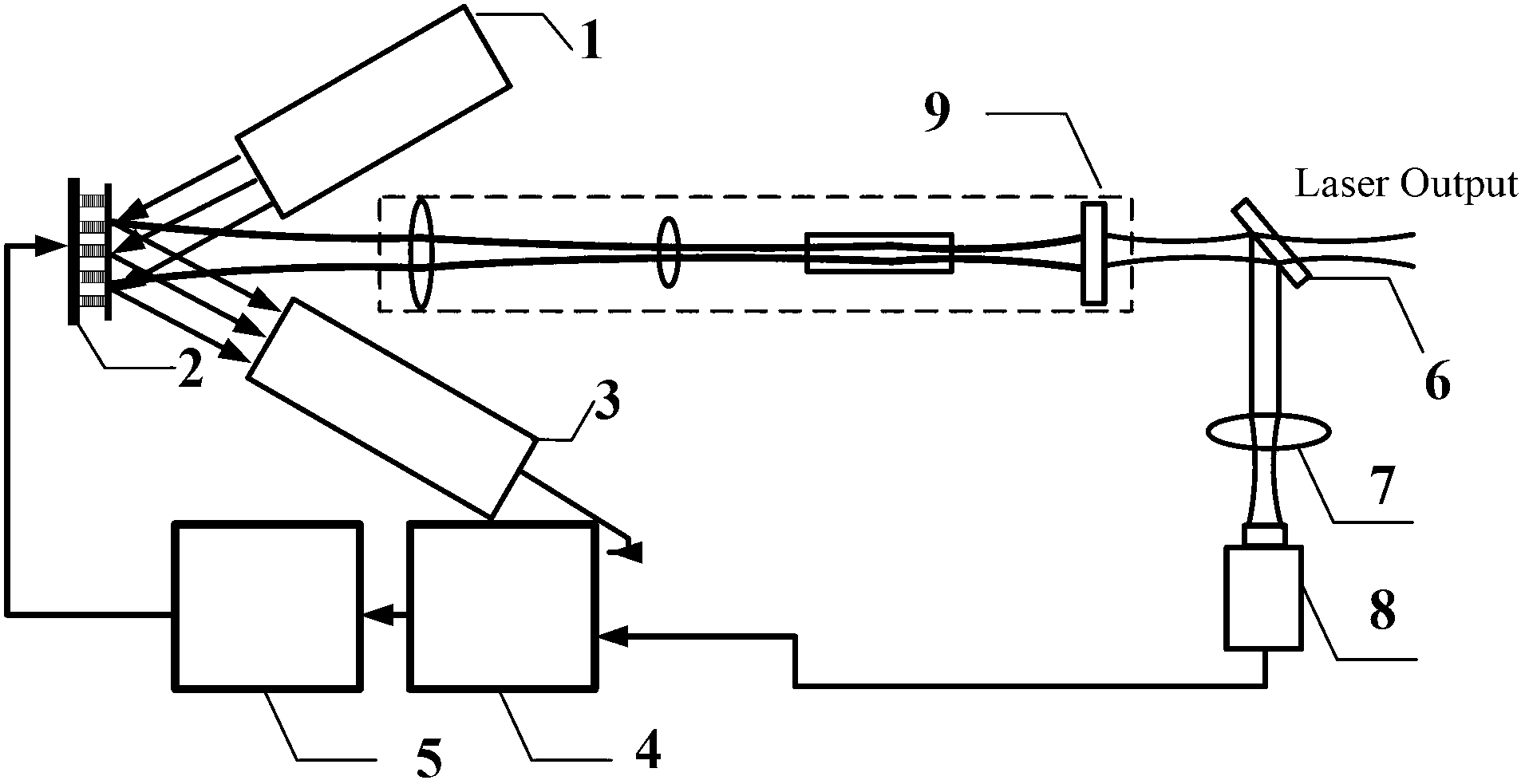
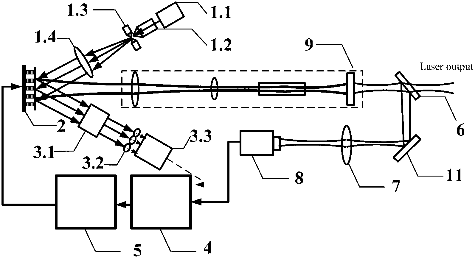
[0025] Such as figure 2 As shown, a schematic diagram of the optical path of an implementation example of the intracavity adaptive optical beam purification system, a parallel light source 1 composed of a 650nm semiconductor laser 1.1, a microscopic objective lens 1.2, a pinhole 1.3, and a collimating lens 1.4, a deformable mirror 2, and a beam shrinker Hartmann sensor 3 composed of device 3.1, microlens array 3.2, camera 3.3, data acquisition and control computer 4, high-voltage amplifier 5, beam splitter 6, focusing lens 7, beam quality diagnostic camera 8, and laser 9.

[0026]A parallel light source composed of a 650nm semiconductor laser 1.1, a microscopic objective lens 1.2, a pinhole 1.3 and a collimating lens 1.4 emits a parallel light beam with uniform light intensity and enters the deformable mirror 2 at 22°. The beam shrinker 3.1 is located about 300 mm behind the deformable mirror, with an aperture of 50 mm, and is coaxial with the 650 nm parallel beam reflected b...


PUM


Abstract

The invention relates to an in-cavity self-adaptive optical beam purification system and a method. The self-adaptive optical beam purification system consists of a parallel light source, a deformable mirror, a Hartmann sensor, a data acquisition and control computer, a high-voltage amplifier, a spectroscope, a focusing lens, a beam quality diagnosis camera and a laser device. During beam purification, the prior surface shape of the deformable mirror is preset at first via the Hartmann sensor, and then the beam is purified in a random optimization control method. By adopting the method, prior data can be utilized effectively, the time for purification of the beam in the cavity can be greatly reduced, and the control stability of the in-cavity beam purification system can be improved.

Description

technical field [0001] The invention relates to an intracavity adaptive optical beam purification system and method, which is suitable for performing intracavity beam purification on resonant cavities whose intracavity distortion is mainly repetitive static distortion and the absolute value of dynamic disturbance distortion is small, and belongs to the field of adaptive optics and laser field. Background technique [0002] The intracavity adaptive optical beam purification system is an adaptive optical system that can track and compensate the distortion in the laser resonator cavity in real time, improve the working performance of the laser, and optimize the output beam energy or beam quality of the laser. Since the first successful application of adaptive optics to CO 2 Compensation of distortion in the laser cavity (see R.H.Freeman et al. Adaptive laser resonator, 1978, Optics Letters), from the source of laser generation - the laser resonator, improves the near-field and...

Claims


Application Information

Patent Timeline
IPC IPC(8): G02B26/06
Inventor 晏虎杨平许冰刘文劲雷翔董理智
Owner INST OF OPTICS & ELECTRONICS - CHINESE ACAD OF SCI
Learn More