
Real-time on-line detection device for working state of cannon photoelectric subsystem

A technology of working status and detection devices, which is applied in the direction of weapon testing, weapon accessories, offensive equipment, etc., can solve problems such as fault location, long repair time, debugging, poor real-time detection, heavy CPU load, etc., and is conducive to real-time online diagnosis , quickly and accurately locate faults, and reduce CPU load

Active Publication Date: 2014-09-17
中国兵器工业第二0五研究所
View PDF4 Cites 0 Cited by
  • Summary
  • Abstract
  • Description
  • Claims
  • Application Information

AI Technical Summary

Problems solved by technology

However, the simulation platform uses a hardened computer as the hardware platform and requires AC220V power supply. Due to the high cost, high power consumption, bulky size, uneasy portability, and complicated installation of the simulation platform, it takes a long time for fault location and repair, especially when it is used in the field. particularly prominent, ultimately affecting the tests of the entire artillery system
In addition, the simulation platform itself uses the PCICAN interface card to realize communication with the photoelectric subsystem, and the interface display adopts the full-screen display mode, and the displayed status information is also limited
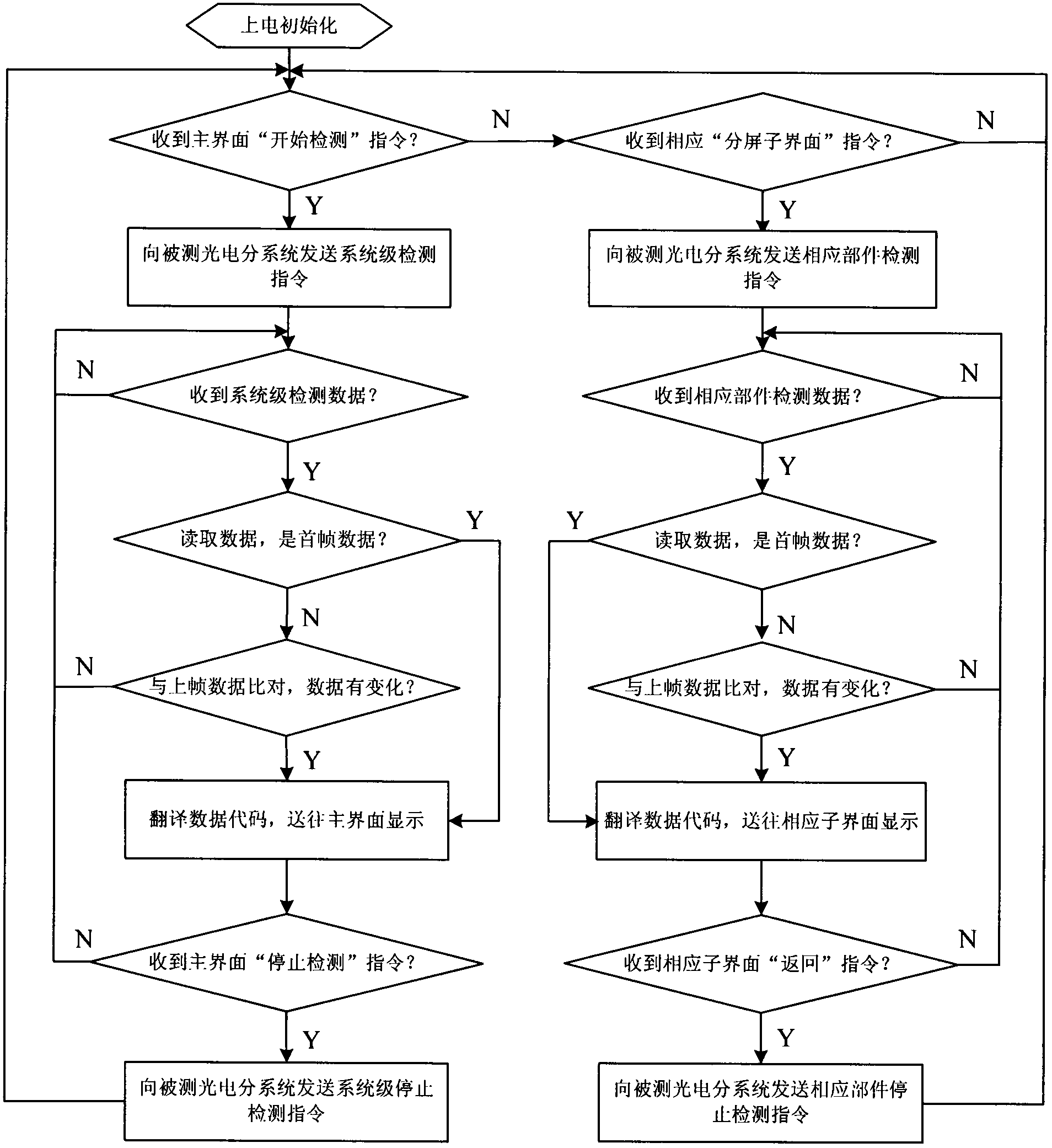
In the detection process, multiple frames of detection data need to be received in one cycle, and the ID determination, code analysis, and screen display of the multi-frame data in this cycle need to be completed before the data of the next cycle comes. Therefore, the bus data volume is large, the CPU load is heavy, and the interface display The refresh rate is low, resulting in poor real-time debugging and detection, and inconvenient use
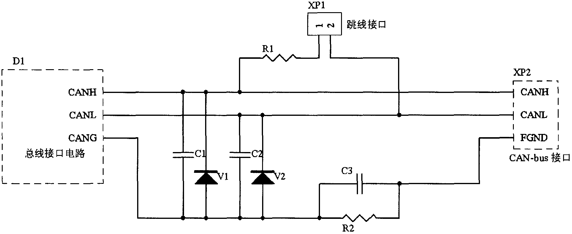
At the same time, since this type of photoelectric subsystem is installed in a limited car body space integrated with many electronic devices, the CAN-bus is in a complex electromagnetic environment, and the PCICAN interface of the simulation platform is easily damaged without an effective protection circuit. Fluctuations due to interference, resulting in false positives of detection information, and even burning the interface chip

Method used


Image

  • Real-time on-line detection device for working state of cannon photoelectric subsystem
  • Real-time on-line detection device for working state of cannon photoelectric subsystem
  • Real-time on-line detection device for working state of cannon photoelectric subsystem

Examples


Embodiment Construction

[0014] The present invention will be further described in detail below in conjunction with the accompanying drawings and preferred embodiments.

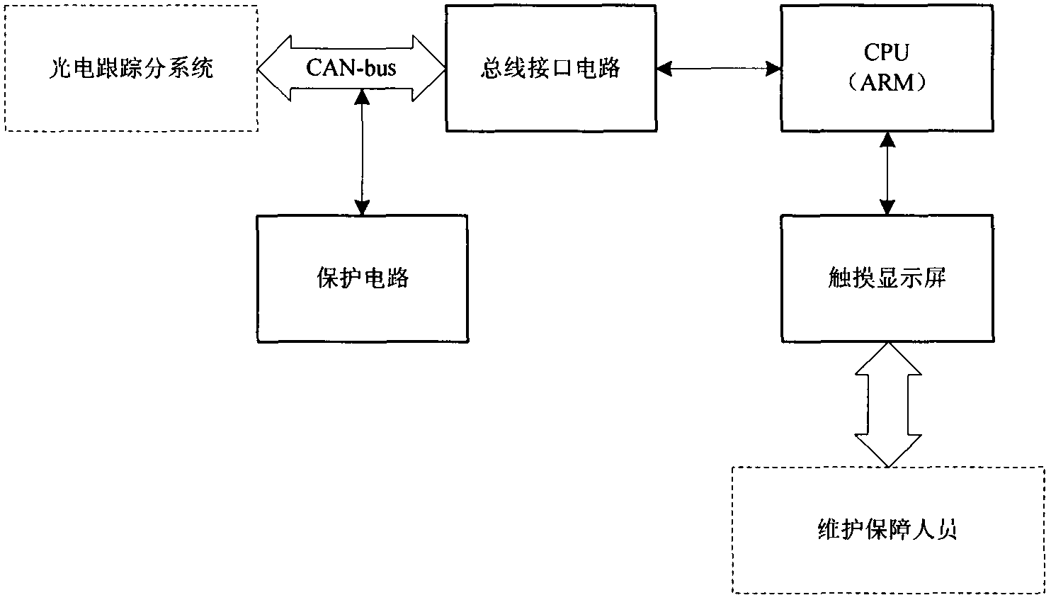
[0015] as figure 1 As shown, the preferred embodiment of the portable real-time online detection device of the present invention adopts the embedded hardware platform with ARM9 as the core, and it includes the CPU, bus interface circuit D1, jumper interface XP1, CAN-bus bus interface XP2, which model is LPC3250, Display, protection circuit. The display adopts a 6.4-inch TFT color LCD touch screen with a resolution of 640x480. The CPU and the bus interface circuit D1 are integrated on a circuit board. -bus bus interface XP2, which can realize the connection with the external power supply and the CAN-bus bus detection interface of the photoelectric subsystem. The original cable connection of the photoelectric subsystem does not need to be changed, and the online detection device of the present invention will not affect the work of ot...


PUM


Abstract

The invention discloses a real-time on-line detection device for the working state of a cannon photoelectric subsystem. In the device, a computer simulation stand based on the Windows XP operating system is changed to be a portable ARM embedded-type platform based on the WinCE6.0 operating system, the miniaturization and the simplification of a large-scale detection device are achieved, and quick mounting and flexible use during an external field test are facilitated; meanwhile, over-voltage protection and filter circuits are added on a CAN bus interface circuit, a chip is effectively prevented from being burnt out, and interferences brought by a complex electromagnetic environment where photoelectric equipment locates can be eliminated; detected contents are divided into a system grade module and a plurality of component grade modules by the CPU in the device, when in use, detection can be performed according to actual requirements and modules, therefore, the load of the CPU and the power consumption of the detection device are reduced, real-time on-line diagnosis to the state of the photoelectric system is facilitated, a failure part can be positioned accurately and quickly, the purpose of quick fault recovery is achieved, and manpower and physical resources are saved.

Description

technical field [0001] The invention belongs to the technical field of fault detection, and relates to a fault detection device for a cannon, in particular to a device capable of real-time on-line detection of the working state of a photoelectric sub-system of a cannon. Background technique [0002] A certain type of photoelectric tracking subsystem (hereinafter referred to as the photoelectric subsystem) is a subsystem of a certain type of artillery system. After the system is jointly debugged or delivered to the troops, it will be uniformly controlled by the artillery integrated management system. In order to reduce the communication load of the bus, the integrated management system has limited display ports for detecting the state information of the photoelectric subsystem, and cannot fully know the internal state information of the photoelectric subsystem, resulting in the inability to detect the status of the photoelectric subsystem in real time during system joint debug...

Claims


Application Information

Patent Timeline
Patent Type & Authority Patents(China)
IPC IPC(8): F41A31/00
Inventor 赵振海张宝宜王小齐邱亚李维杰刘鑫孟海江梁晓东慕巍王世林许丽蓉
Owner 中国兵器工业第二0五研究所
Learn More