Air humidification cabinet and use method thereof
A technology of air humidification and water-receiving plate, which is applied in the field of daily necessities and can solve the problem of inability to humidify indoor air.
- Summary
- Abstract
- Description
- Claims
- Application Information
AI Technical Summary
Problems solved by technology
Method used
Image

Examples
specific Embodiment 1
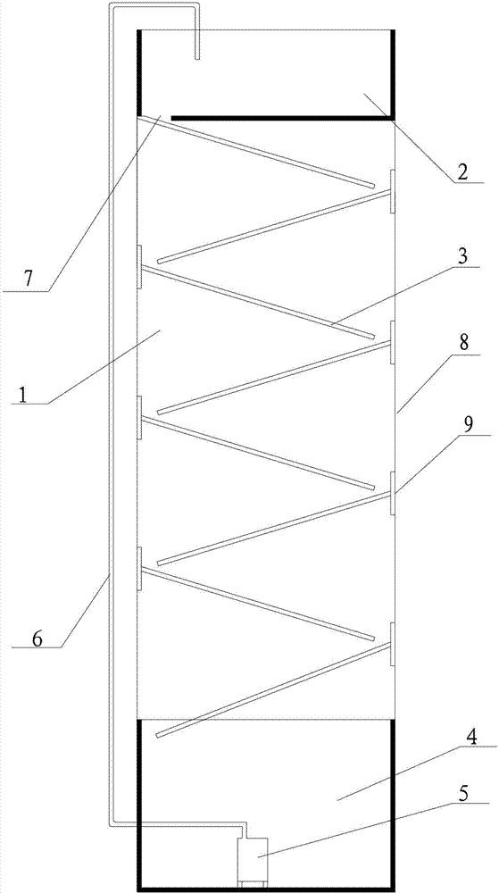
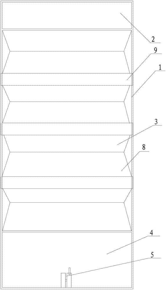
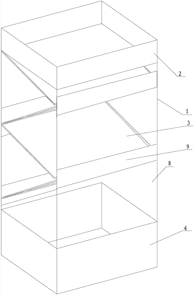
[0067] Air humidifying cabinet of the present invention, as figure 1 , 2 As shown in and 3, the first water tank 2 is located at the top of the frame body 1, the second water tank 4 is located at the bottom of the frame body 1, and the first water tank 2 is connected with a water pipe 6 for water inlet ;
[0068] The bottom of the first water tank 2 is provided with a water outlet 7;
[0069] There are multiple water bearing plates 3, one side of the water bearing plate 3 is fixed on the side wall 9 of the frame body 1, the side wall is provided with a plurality of evaporation ports 8, two adjacent In the water bearing plate 3, the projection on the horizontal plane of the water bearing plate 3 on the upper side away from the side wall connected to it is within the range of the horizontal projection of the water bearing plate 3 below it Inside, fix the distance between the side wall 9 of the water bearing plate 3 and the side wall opposite to it, and the length ratio of the...
specific Embodiment 2
[0074] In the air humidifying cabinet of the present invention, the first water tank 2 is located on the top of the frame body 1, the second water tank 4 is located at the bottom of the frame body 1, and the first water tank 2 is connected to the water pipe for water inlet. 6 connections;
[0075] The bottom of the first water tank 2 is provided with a water outlet 7;
[0076] There are multiple water bearing plates 3, one side of the water bearing plate 3 is fixed on the side wall 9 of the frame body 1, the side wall is provided with a plurality of evaporation ports 8, two adjacent In the water bearing plate 3, the projection on the horizontal plane of the water bearing plate 3 on the upper side away from the side wall connected to it is within the range of the horizontal projection of the water bearing plate 3 below it Inside, fix the distance between the side wall 9 of the water bearing plate 3 and the side wall opposite to it, and the length ratio of the horizontal projec...
specific Embodiment 3
[0081] In the air humidifying cabinet of the present invention, the first water tank 2 is located on the top of the frame body 1, the second water tank 4 is located at the bottom of the frame body 1, and the first water tank 2 is connected to the water pipe for water inlet. 6 connections;
[0082] The bottom of the first water tank 2 is provided with a water outlet 7;
[0083] There are multiple water bearing plates 3, one side of the water bearing plate 3 is fixed on the side wall 9 of the frame body 1, the side wall is provided with a plurality of evaporation ports 8, two adjacent In the water bearing plate 3, the projection on the horizontal plane of the water bearing plate 3 on the upper side away from the side wall connected to it is within the range of the horizontal projection of the water bearing plate 3 below it Inside, fix the distance between the side wall 9 of the water bearing plate 3 and the side wall opposite to it, and the length ratio of the horizontal projec...
PUM
 Abstract
Description
Claims
Application Information
 - R&D
- Intellectual Property
- Life Sciences
- Materials
- Tech Scout
- Unparalleled Data Quality
- Higher Quality Content
- 60% Fewer Hallucinations
Browse by: Latest US Patents, China's latest patents, Technical Efficacy Thesaurus, Application Domain, Technology Topic, Popular Technical Reports.
© 2025 PatSnap. All rights reserved.Legal|Privacy policy|Modern Slavery Act Transparency Statement|Sitemap|About US| Contact US: help@patsnap.com