Hybrid construction machine
A construction machinery and hybrid technology, applied in hybrid vehicles, fluid hybrid vehicles, power units, etc., can solve the problems of insufficient torque of the upper rotating body, workability (decreased workability, inability to obtain a sense of operation, etc.) Achieving a good sense of operation and work ability, ensuring the effect of operation sense and work ability
- Summary
- Abstract
- Description
- Claims
- Application Information
AI Technical Summary
Problems solved by technology
Method used
Image
Examples
no. 1 approach
[0112] ~Structure of Hydraulic Excavator~
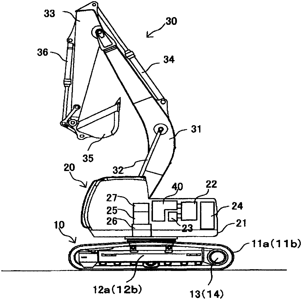
[0113] figure 1 A side view of the hybrid hydraulic excavator according to the first embodiment of the present invention is shown.
[0114] exist figure 1 Among them, the hybrid hydraulic excavator includes: an undercarriage 10 ; an upper revolving unit 20 rotatably provided on the undercarriage 10 ; and an excavating mechanism 30 .
[0115] The undercarriage body 10 consists of a pair of crawler belts 11a, 11b and crawler frames 12a, 12b (in figure 1 Only one side is shown in the figure), a pair of right and left traveling hydraulic motors 13, 14 for independently driving and controlling each crawler belt 11a, 11b, and a reduction mechanism thereof.
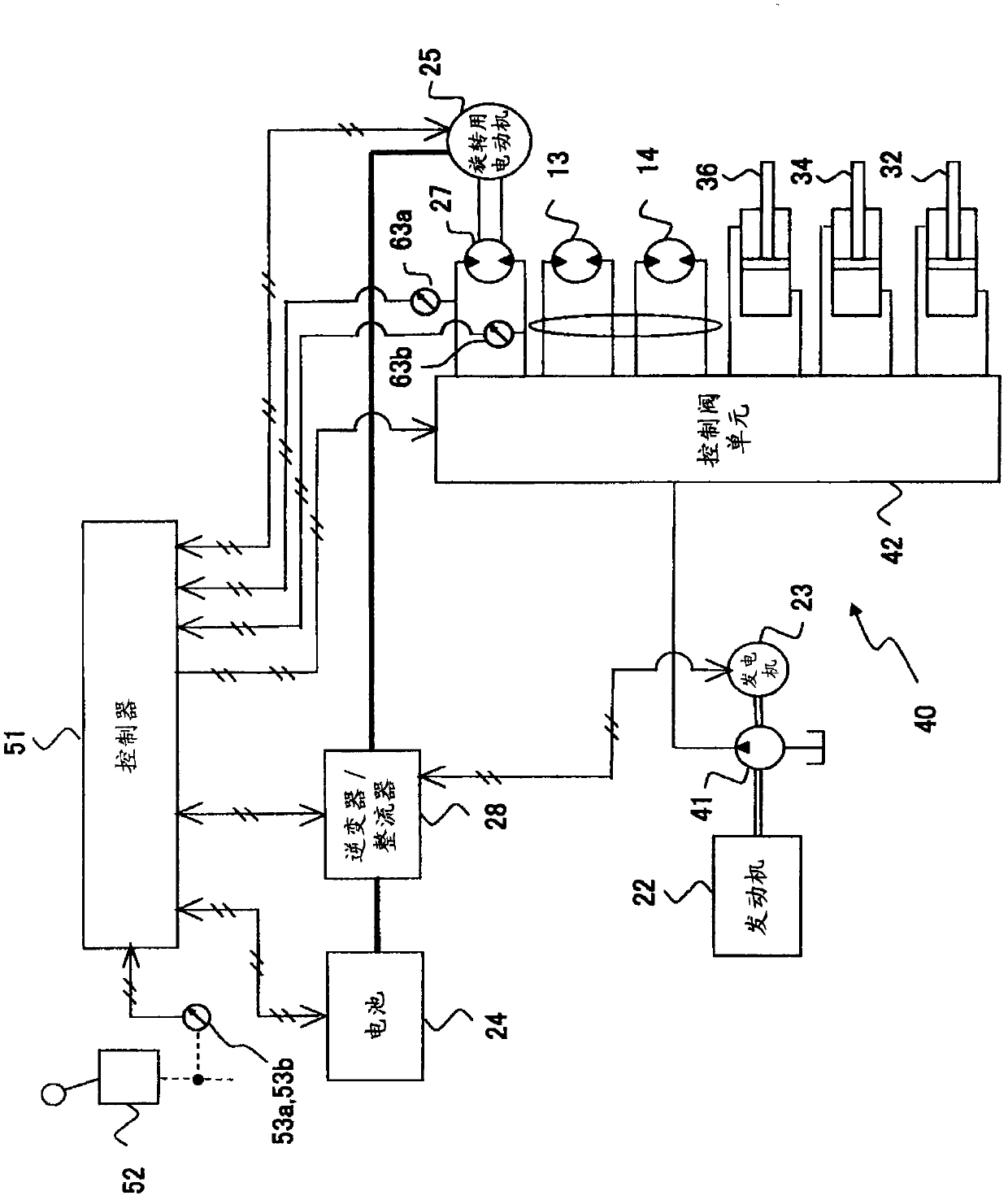
[0116] The upper rotating body 20 is composed of the following components: a rotating frame 21; an engine 22 as a prime mover installed on the rotating frame 21; a generator 23 driven by the engine 22; for storing the electric power generated by the generator 23 The electric motor ...
no. 2 approach
[0176] use Figure 16 A hybrid hydraulic excavator according to a second embodiment of the present invention will be described. In this embodiment, when the electric motor 25 for turning is not driven, in order to increase the braking torque, the combined throttling of the meter-out part of the direction and flow control valve 37 and the throttle part of the auxiliary valve is used to make the hydraulic pressure for turning The meter-out pressure rise of the motor is controlled.
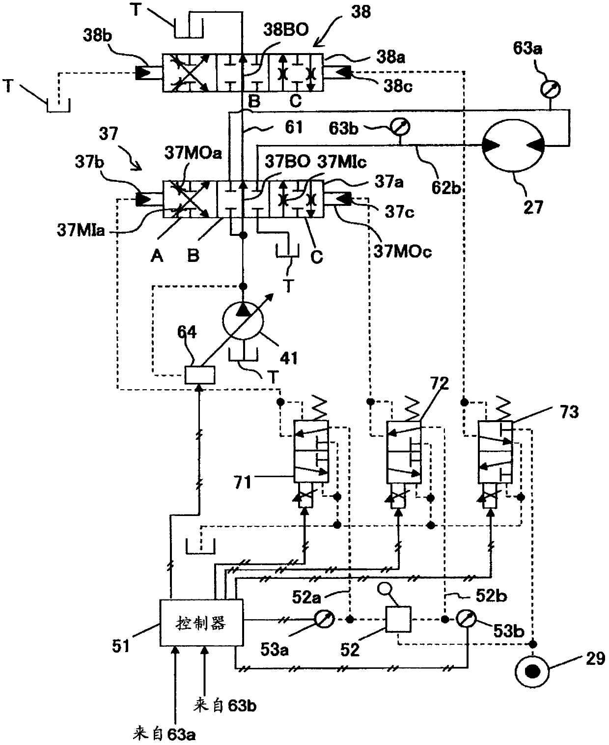
[0177] Figure 16 It is a figure which shows the detail of the rotary hydraulic system of the hydraulic circuit apparatus concerning 2nd Embodiment of this invention. In the figure, for Figure 1 ~ Figure 3 The same structural elements are assigned the same reference signs.
[0178] exist Figure 16 In, instead of the first embodiment's image 3 The electromagnetic proportional pressure reducing valves 71 and 72 shown, the rotary hydraulic system has a meter-out auxiliary valve 44 and an electr...
no. 3 approach
[0182] use Figure 17 ~ Figure 19 A hybrid hydraulic excavator according to a third embodiment of the present invention will be described. In this embodiment, in order to increase the driving torque of the hydraulic motor 27 for swing when the electric swing motor 25 is not driven, the bypass throttle portion of the direction and flow control valve 37 is controlled in the closing direction, thereby making the The rotation is controlled so that the meter-in pressure of the hydraulic motor 27 increases.
[0183] Figure 17 It is a figure which shows the detail of the rotary hydraulic system of the hydraulic circuit apparatus concerning 3rd Embodiment of this invention. In the figure, for Figure 1 ~ Figure 3 The same structural elements are assigned the same reference signs.
[0184] exist Figure 17 , instead of the first embodiment image 3 The shown intermediate bypass reversing valve 38, controller 51, operating device 52, pressure sensors 53a, 53b, electromagnetic pro...
PUM
 Abstract
Description
Claims
Application Information
 - R&D
- Intellectual Property
- Life Sciences
- Materials
- Tech Scout
- Unparalleled Data Quality
- Higher Quality Content
- 60% Fewer Hallucinations
Browse by: Latest US Patents, China's latest patents, Technical Efficacy Thesaurus, Application Domain, Technology Topic, Popular Technical Reports.
© 2025 PatSnap. All rights reserved.Legal|Privacy policy|Modern Slavery Act Transparency Statement|Sitemap|About US| Contact US: help@patsnap.com


