
Multi-station numerically-controlled wood lathe

A woodworking lathe and multi-station technology, applied in the direction of woodworking lathes, manufacturing tools, wood processing equipment, etc., can solve the problems of inconvenient installation of woodworking workpieces, affecting the processing of workpieces, and low degree of automation, so as to save manpower and electric energy costs, improve Processing efficiency and high degree of automation

Active Publication Date: 2012-10-03
NANTONG OUKE CNC EQUIP CO LTD
View PDF10 Cites 7 Cited by
  • Summary
  • Abstract
  • Description
  • Claims
  • Application Information

AI Technical Summary

Problems solved by technology

[0002] Existing lathes for processing woodworking workpieces generally need to place the wood pieces to be processed at the position of the processing tool for processing. The existing lathes only have one to two processing stations, because some wood pieces are processed parts produced in large quantities. , or standard parts, so the processing efficiency is low. At the same time, most lathes use manual operation or adjust the position of the workpiece, and the degree of automation is low. In addition, the existing two-station woodworking lathe, such as Chinese patent 200720158288.0, which discloses The two processing stations are designed in a vertical direction, which is not convenient for installing woodworking workpieces, and if the woodworking workpieces on the upper station slip or break, it will affect the processing of the workpieces at the lower station, resulting in unstable operation

Method used


Image

  • Multi-station numerically-controlled wood lathe
  • Multi-station numerically-controlled wood lathe
  • Multi-station numerically-controlled wood lathe

Examples


Embodiment Construction

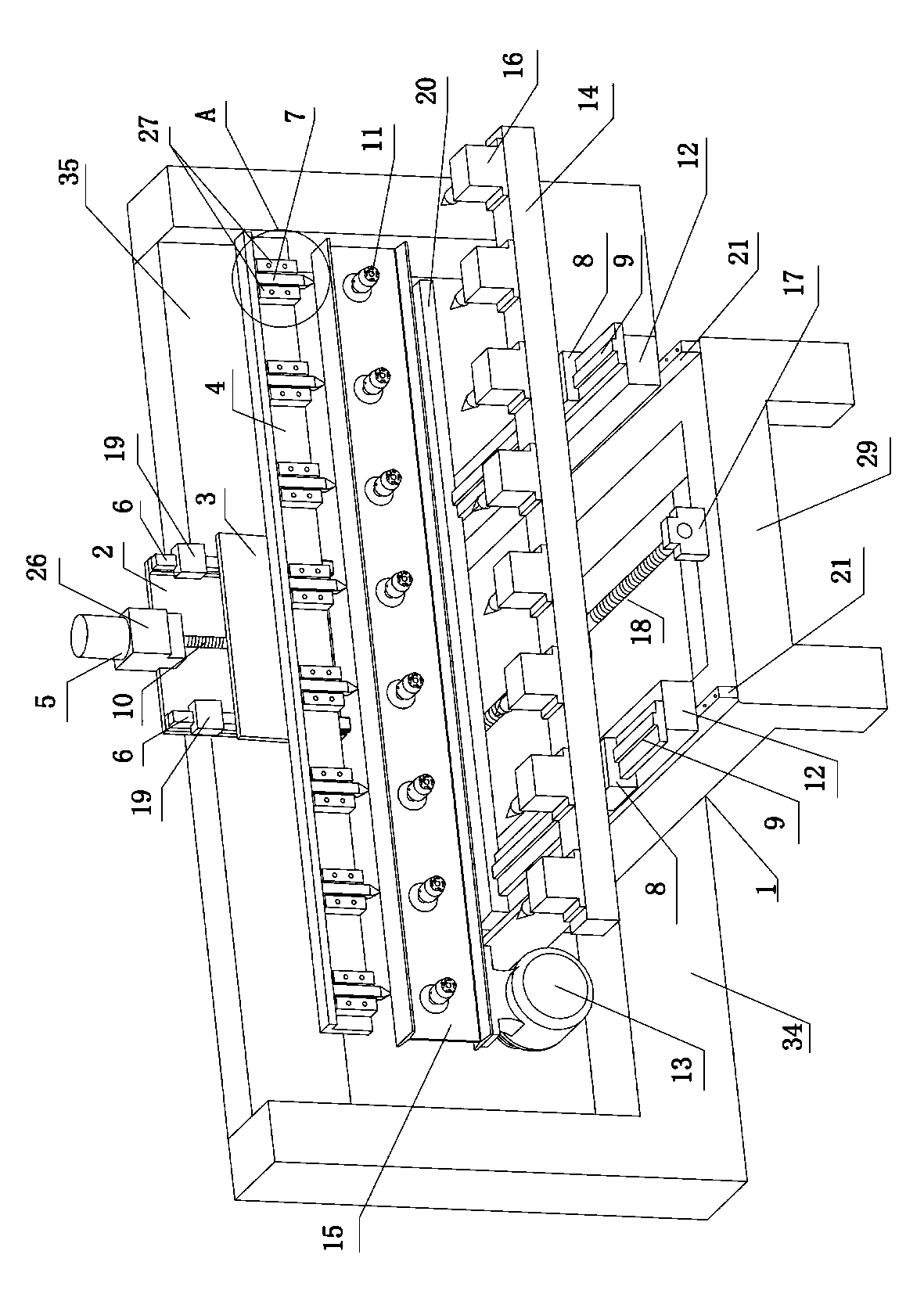
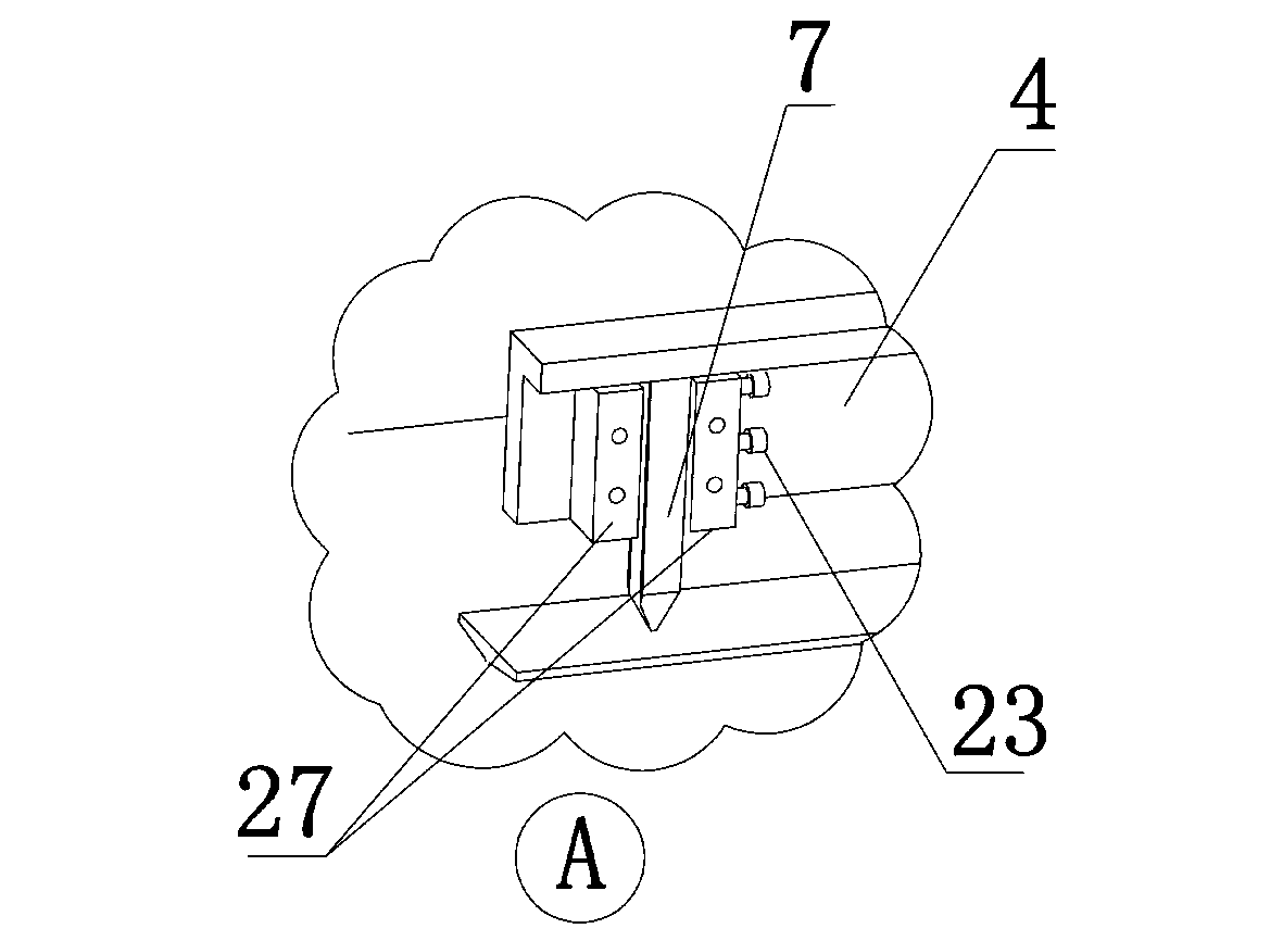
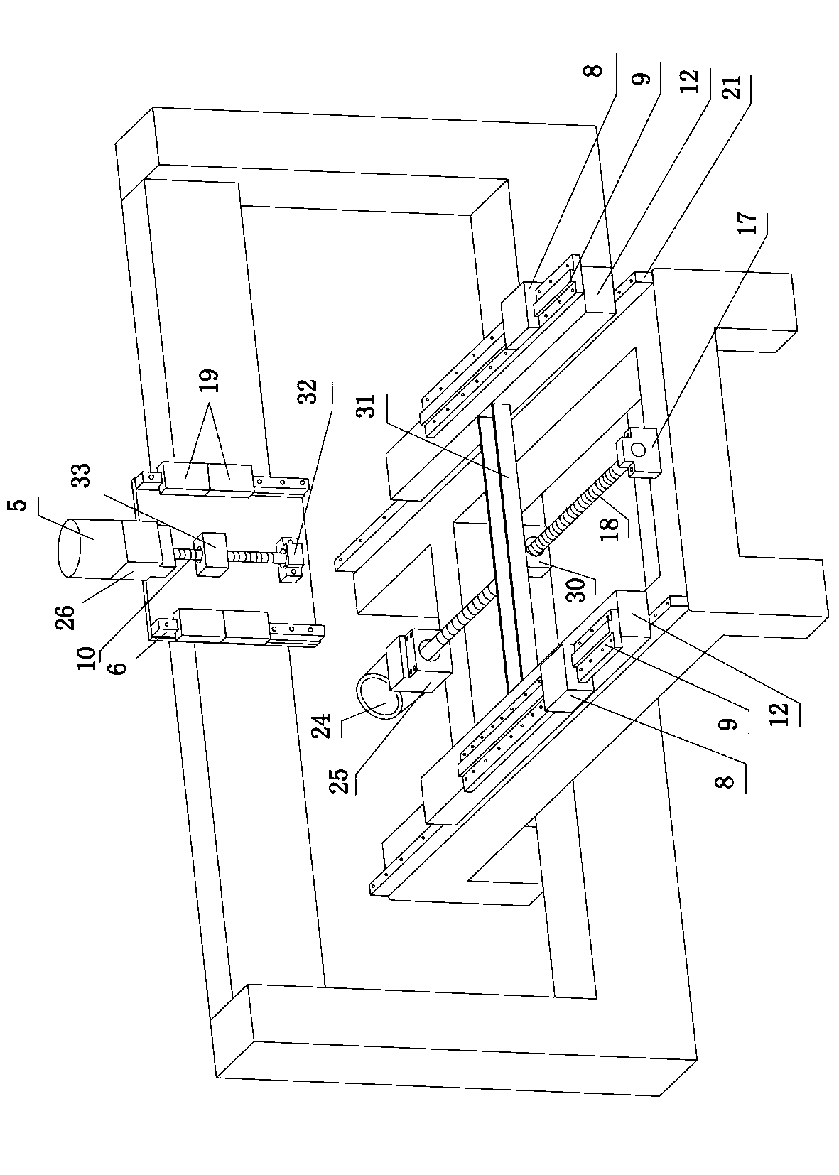
[0023] Refer to attached figure 1 , 2 , 3, 4, a multi-station CNC woodworking lathe, including a frame (1) and a crossbeam (35) fixed on the top of the frame and arranged horizontally and horizontally, the frame (1) consists of an H-shaped base (29) and a U Base (34) constitutes, on the side of crossbeam (35), be provided with the tool rest (4) that is used to install several cutters (7), between crossbeam (35) and cutter rest (4), be provided with and be fixed on crossbeam (35) ) plate (2), on the plate (2) is provided with a vertical drag block (19) connected to the vertically arranged vertical guide rail (6), and at the same time, between the beam (35) and the tool holder (4) is provided with a The vertical dragging plate (3) connected with the vertical dragging block (19), the above-mentioned tool holder (4) is fixed on the vertical dragging plate (3), and the vertical dragging block (19) is set on the plate (2) to drive along the vertical guide rail (6) Moving driving ...


PUM


Abstract

The invention relates to a multi-station numerically-controlled wood lathe and belongs to the technical field of a woodworking machine. The multi-station numerically-controlled wood lathe comprises a rack, and a cross beam fixed above the rack and horizontally transversely arranged, wherein the rack is comprises an H-shaped base and a U-shaped base; a toolframe for mounting a plurality of tools is arranged on the side of the cross beam; a plate block fixed on the cross beam is arranged between the cross beam and the toolframe; a vertical dragging block connected with a vertically arranged vertical guide rail is arranged on the plate body; simultaneously, a vertical dragging plate connected with the vertical dragging block is arranged between the cross beam and the toolframe; the toolframe is fixed on the vertical dragging plate; a drive mechanism 1 for driving the vertical dragging block to move along the vertical guide rail is arranged on the plate block; two horizontally longitudinally arranged longitudinal guide rails are arranged on the H-shaped base; a sliding block 2 capable of sliding along the longitudinal direction of the guide rail is arranged on the longitudinal guide rail; workpiece clamping devices of which the quantity is the same as that of the tools are arranged on the sliding block 2; and a drive mechanism 2 capable of driving the sliding block 2 to move along the longitudinal guide rail is arranged on the H-shaped base.

Description

technical field [0001] The invention relates to a multi-station numerically controlled woodworking lathe, which belongs to the technical field of woodworking machinery. Background technique [0002] Existing lathes for processing woodworking workpieces generally need to place the wood pieces to be processed at the position of the processing tool for processing. The existing lathes only have one to two processing stations, because some wood pieces are processed parts produced in large quantities. , or standard parts, so the processing efficiency is low. At the same time, most lathes use manual operation or adjust the position of the workpiece, and the degree of automation is low. In addition, the existing two-station woodworking lathe, such as Chinese patent 200720158288.0, which discloses The two processing stations are designed in a vertical direction, which is not convenient for installing woodworking workpieces, and if the woodworking workpieces on the upper station slip ...

Claims


Application Information

Patent Timeline
IPC IPC(8): B27C7/00B27C7/06
Inventor 张程陈海涛王玉波
Owner NANTONG OUKE CNC EQUIP CO LTD
Learn More