


Quick Research
Generate reliable direction feasibility study reports for your R&D in just a few steps.

Technical Q&A
Discover and master advanced knowledge NOW. Basics, ideas, possibilities, all at once.

Find Solutions
As an expert in R&D theories, this can generate solutions to your technical problems instantly.

Evaluate Feasibility
Analyze your overall solution with one click, know your potential R&D risks in advance.

Monitor Landscape
Get weekly tech updates, stay abreast of the latest tech innovations and key insights.
Pick-up method of die bonder and die bonder
一种裸片粘接机、裸片的技术,应用在胶粘剂、电气元件、电固体器件等方向,能够解决拾取错误增多、拾取不稳定等问题,达到可靠剥离的效果
- Summary
- Abstract
- Description
- Claims
- Application Information
AI Technical Summary
Problems solved by technology
Method used
Image

Examples
Embodiment 1
[0036] Hereinafter, embodiments of the present invention will be described based on the drawings.
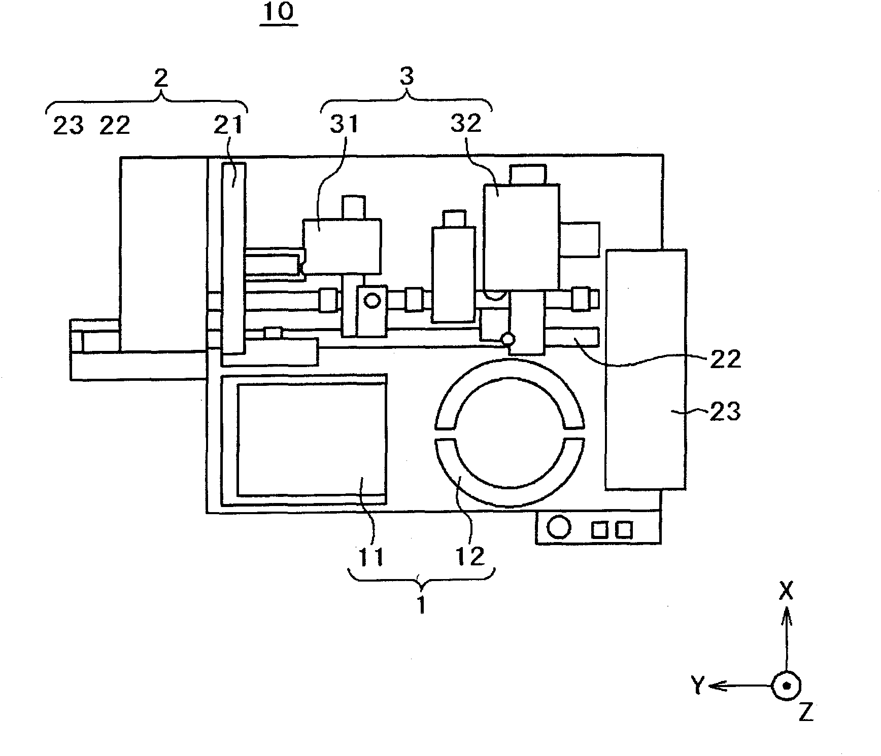
[0037] figure 1 It is a conceptual diagram of the die bonder 10 using one embodiment of the pick-up method and pick-up apparatus of this invention seen from above. The die bonder 10 roughly includes a wafer supply unit 1 , a workpiece supply and conveyance unit 2 , and a die bonding unit 3 .
[0038]The workpiece supply and conveyance unit 2 has a stacker 21 , a frame feeder 22 , and an unloader 23 . The workpieces (lead frames) supplied from the stacker 21 to the frame feeder 22 are conveyed to the unloader 23 through two processing positions on the frame feeder 22 .
[0039] The die attach part 3 has a preliminary processing part 31 and a bonding head part 32 . The preliminary processing unit 31 applies a die adhesive to the workpiece conveyed by the frame feeder 22 . The bonding head 32 picks up the die from the picker 12 and rises to move the die in parallel to the bondi...
Embodiment 2
[0077] according to Figure 9 and Figure 10 , Embodiment 2 of the present invention will be described. also, Figure 1 ~ Figure 4 , Figure 6 and Figure 7 Also used in Example 2. Figure 9 It is a flowchart showing the processing flow of the pick-up operation according to the embodiment of the present invention. in addition Figure 10 It is a diagram for explaining the correction of the tension at the time of picking up the central part and the peripheral part of the wafer in the wafer ring according to one embodiment of the present invention.
[0078] In Example 2 of the present invention, the load (reaction force) at the time of ejection was measured, and the amount of ejection could be changed so that the load at the time of ejection was constant.
[0079] exist Figure 10 In, through the upper and lower mechanism 1002 (refer to Figure 4 (a) working body 53 and drive shaft 57) push out the block main body upwards (refer to Figure 4 (a)) to perform ejection, th...
PUM
 Abstract
Description
Claims
Application Information
 - R&D Engineer
- R&D Manager
- IP Professional
- Industry Leading Data Capabilities
- Powerful AI technology
- Patent DNA Extraction
Browse by: Latest US Patents, China's latest patents, Technical Efficacy Thesaurus, Application Domain, Technology Topic, Popular Technical Reports.
© 2024 PatSnap. All rights reserved.Legal|Privacy policy|Modern Slavery Act Transparency Statement|Sitemap|About US| Contact US: help@patsnap.com