Cradle pressurizing component

A technology of cradles and components, which is applied in the direction of textiles and papermaking, drafting equipment, spinning machines, etc. It can solve the problems of inability to ensure that the top rollers and rollers are parallel, the quality of yarn is difficult to control, and the increase in manufacturing costs, etc., to achieve a reasonable structure , good parallelism, and the effect of improving parallelism

Active Publication Date: 2015-01-07
常州市同和纺织机械制造有限公司
View PDF8 Cites 0 Cited by
  • Summary
  • Abstract
  • Description
  • Claims
  • Application Information

AI Technical Summary

Problems solved by technology

In the above structure, the top roller seat is movably arranged in the top roller seat, and the top roller seat is only limited by the guides on its side. Because there is a certain floating gap between the top roller seat and the pressurization seat, when the The rack handle is pressed down so that when the cradle pressurizing device is in working condition, the top roller seat is in a floating position, so the parallelism of the top rollers can only be guaranteed by the manufacturing and assembly accuracy of the pressurizing components, which will not only increase the manufacturing cost, and there is no guiding mechanism on the top roller shaft when the top roller seat is installed, the size of the top roller claw bayonet of the top roller seat will change after long-term use, and it is impossible to ensure that the top roller seat can keep the top rollers and rollers parallel, and the yarn quality is not easy control

Method used


Image

  • Cradle pressurizing component
  • Cradle pressurizing component
  • Cradle pressurizing component

Examples


Embodiment Construction

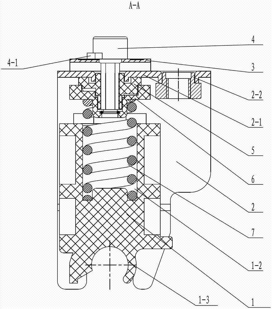
[0018] See Figure 1-7 As shown, the cradle pressurization assembly of the present invention includes a parallel support 2, a top roller seat 1, a spring 7 and a pressure regulating mechanism. The pressurizing assembly is installed at the front, middle, and rear of the lower part of the cradle body 11. The three sets of pressurizing assemblies respectively control the front, middle, and rear three top rollers 8, while the cradle handle 10 and the cradle seat 12 are hinged on the cradle body 11. , by three top rollers 8 pressing respective corresponding rollers 13, a certain frictional force is generated between the top rollers 8 and rollers 13 to realize spinning.

[0019] See Figure 1~2 As shown, the parallel support 2 of the present invention has a top plate 2-1 and side plates 2-4 positioned on both sides of the top plate 2-1, and the top plate 2-1 of the parallel support 2 is provided with a via hole for the pressure regulating rod 4 to pass through and The mounting hol...


PUM


Abstract

The invention relates to a cradle pressurizing component, which comprises a parallel bracket, a roller seat, a spring and a pressure regulating mechanism, wherein a through hole and a mounting hole are arranged in the top plate of the parallel bracket, the upper parts of two side plates of the parallel bracket are provided with upper notches, and the lower parts of the two side plates of the parallel bracket are provided with lower notches; the bottom of the roller seat is provided with a roller claw, and guiding bulges on two sides of the roller seat are arranged in the upper notches arranged on the upper parts of the two side plates and can move up and down; the pressure regulating mechanism comprises an indicator board, a pressure regulating rod, an upper pressure regulating block and a lower pressure regulating block, the indicator board is arranged on the parallel bracket, the pressure regulating rod with a pressure pointer is connected with the upper pressure regulating block, the indicator board is provided with a gears indicating sign, the upper pressure regulating block is arranged in the lower pressure regulating block and can be rotated, one upper pressure regulating plane of the upper pressure regulating block is connected with one lower pressure regulating plane of the lower pressure regulating block, and the spring arranged in the roller seat is propped on the lower pressure regulating block. The cradle pressurizing component disclosed by the invention has a reasonable structure, the pressure regulating operation is simple and convenient, and the requirement on degree of parallelism of the roller can be met.

Description

technical field [0001] The invention relates to a cradle pressurizing assembly, which belongs to the technical field of cradle pressurizing devices for ring spinning frames. Background technique [0002] The cradle pressurizing device used for ring spinning frame is mainly composed of cradle body, cradle seat, handle, and front, middle and back three pressurizing components. The pole shaft hole on the cradle seat is installed on the pole shaft, and the front, middle and rear pressure components are respectively installed under the cradle body. Each pressure component is equipped with a roller claw, which is connected to each leather The top rollers on the roller claws press the respective corresponding rollers. When working, the cradle handle and the cradle body, and under the action of their respective pressurizing components, press the front, middle and rear three top rollers against the respective corresponding rollers, so that A certain frictional force is generated bet...

Claims


Application Information

Patent Timeline
Patent Type & Authority Patents(China)
IPC IPC(8): D01H5/46
Inventor 屈臻辉唐国新胥惠英徐涛
Owner 常州市同和纺织机械制造有限公司
Why Eureka
Try Eureka