Ion source of proton transfer mass spectrometer
A proton transfer and ion source technology, which is applied in the field of mass spectrometry ionization source devices to achieve the effects of improving repulsion and extraction efficiency, improving ion transmission efficiency, and high production efficiency
- Summary
- Abstract
- Description
- Claims
- Application Information
AI Technical Summary
Problems solved by technology
Method used
Image
Examples
Embodiment 1
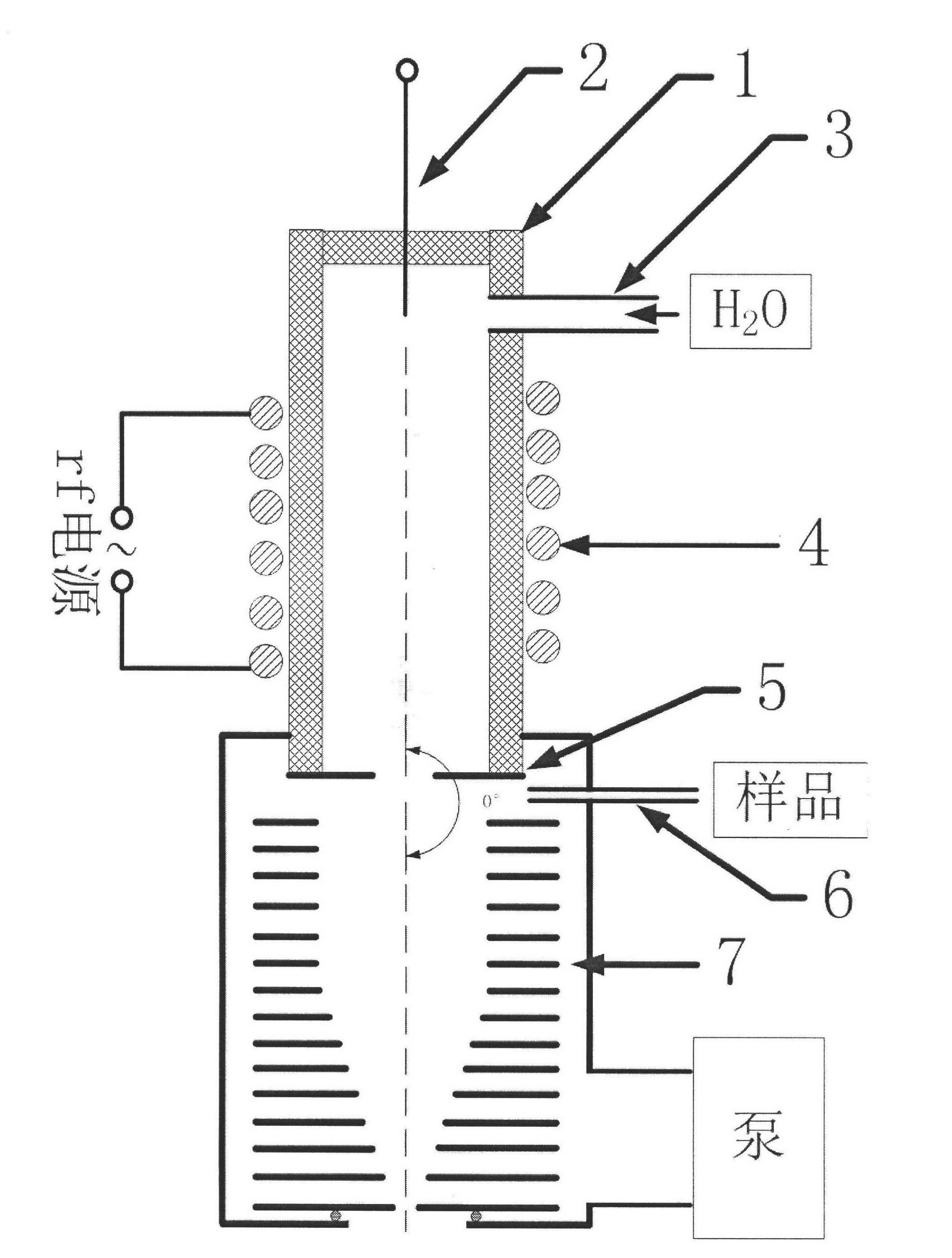
[0023] Example 1, see figure 1 Shown:
[0024] A proton transfer mass spectrometry ion source of the present invention comprises an insulating medium cavity 1, a repeller electrode 2, a gas inlet 3, a radio frequency coil 4, an extraction electrode 5, a sample inlet 6 and an ion funnel type drift tube 7, the insulating medium cavity 1. The upper end is closed, the lower end is open, and connected to the lead-out electrode 5; the radio frequency coil 4 surrounds the middle part of the insulating medium cavity 1; the gas inlet 3 is provided between the radio frequency coil 4 and the closed end of the insulating medium cavity 1 The repelling electrode 2 is located inside the closed end of the insulating medium cavity 1, and is located above the radio frequency coil 4; the insulating medium cavity 1 is inserted into the inside of the upper end of the ion funnel drift tube 7 and sealed The sample inlet 6 is located on the upper side wall of the ion funnel drift tube 7, and is loca...
Embodiment 2
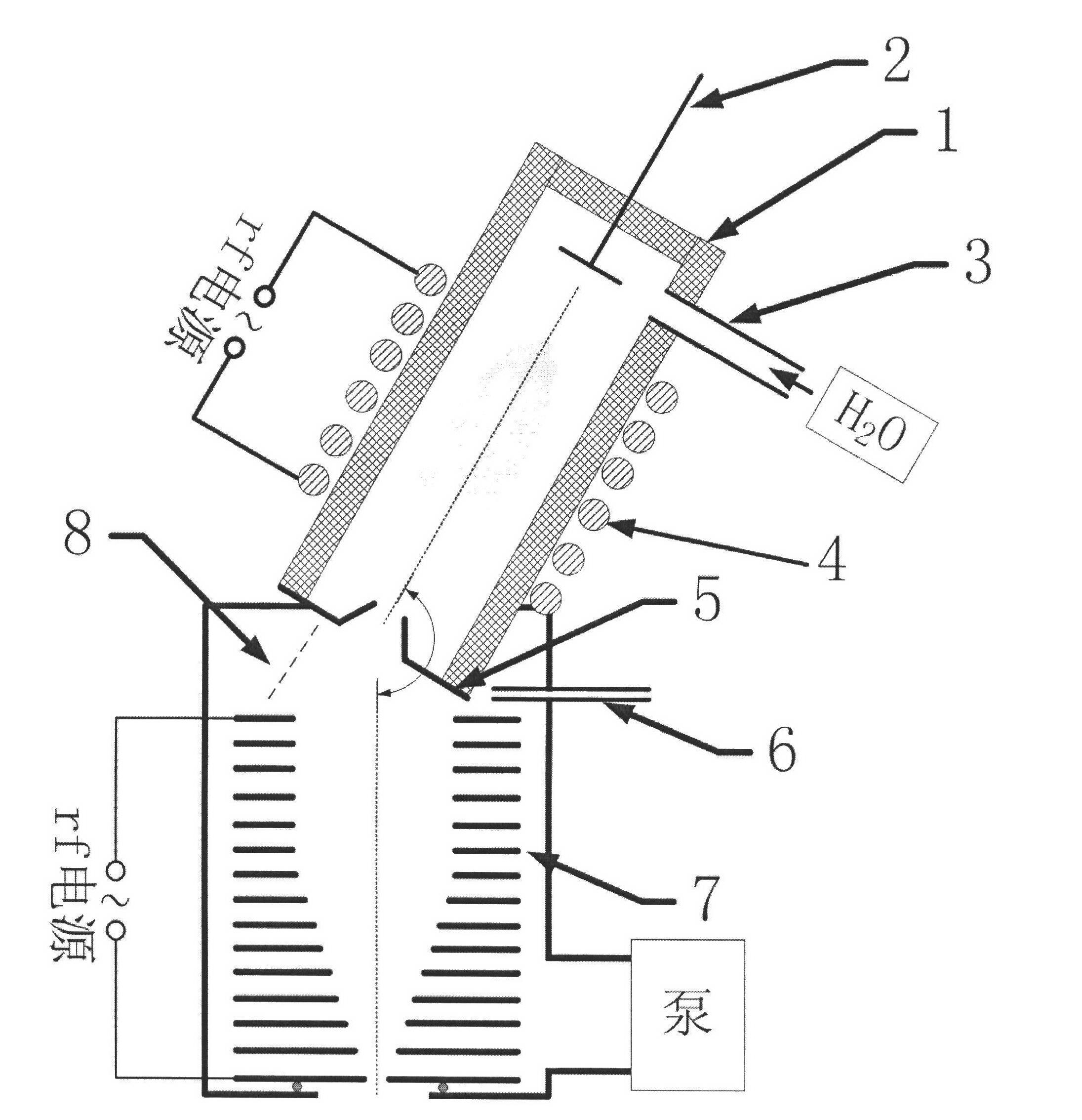
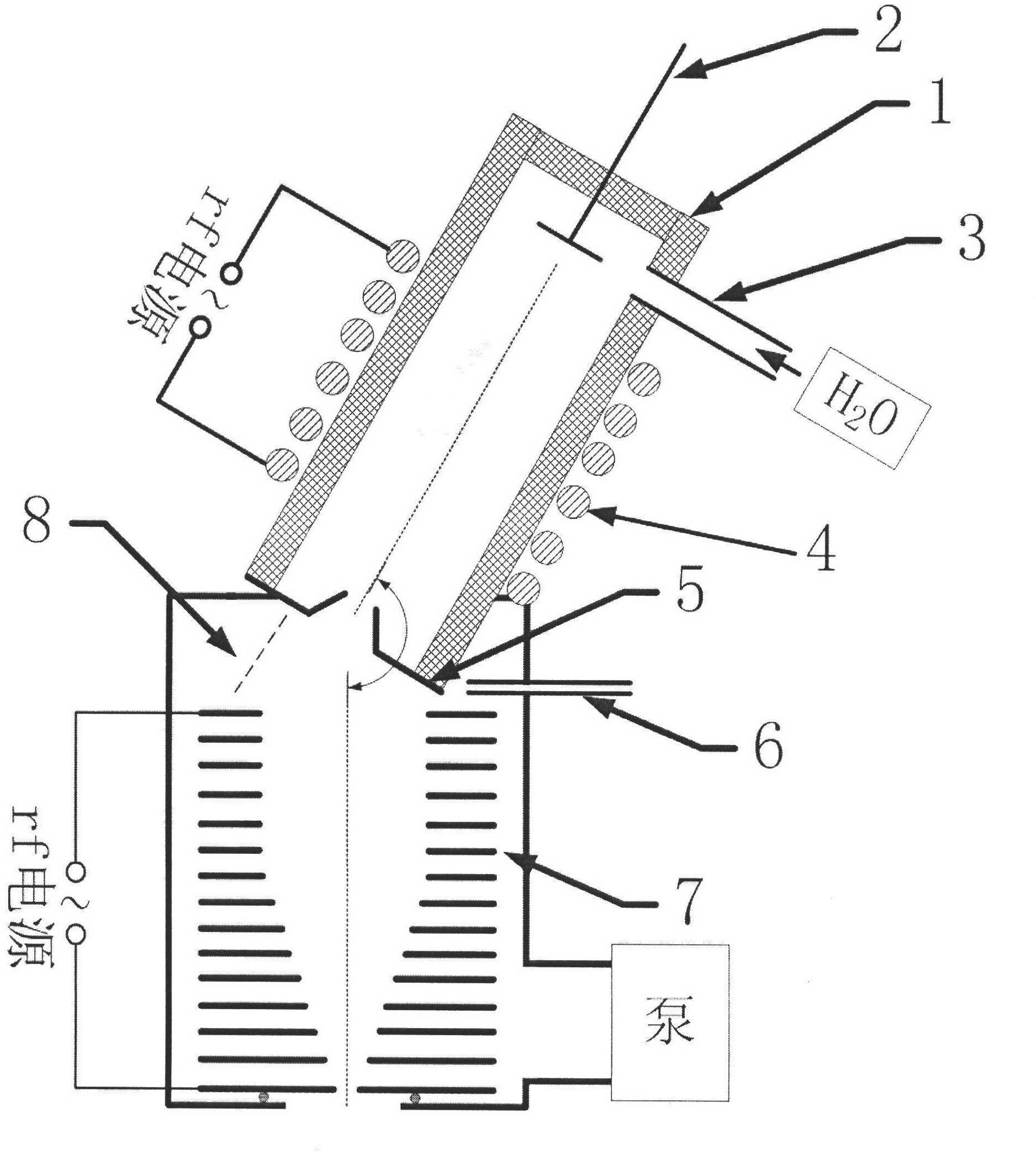
[0027] Example 2, see figure 2 Shown:
[0028] A proton transfer mass spectrometry ion source of the present invention comprises an insulating medium cavity 1, a repeller electrode 2, a gas inlet 3, a radio frequency coil 4, an extraction electrode 5, a sample inlet 6 and an ion funnel type drift tube 7, the insulating medium cavity 1. The upper end is closed, and the lower end is open and connected to the lead-out electrode 5; the radio frequency coil 4 surrounds the middle part of the insulating medium cavity 1; the gas inlet 3 is arranged between the radio frequency coil 4 and the closed end of the insulating medium cavity 1 on the side wall; the repelling electrode 2 is located inside the closed end of the insulating medium cavity 1, and is located above the radio frequency coil 4; the insulating medium cavity 1 is inserted into the inside of the upper end of the ion funnel drift tube 7 and sealed; The sample inlet 6 is located on the upper side wall of the ion funnel dr...
Embodiment 3
[0031] Example 3, see figure 1 Shown:
[0032]The structure of this embodiment is basically the same as that of Embodiment 1. The material of the insulating medium chamber 1 is glass, the inner diameter is 2mm, the length is 20mm, the gas pressure in the chamber is 200Pa, the carrier gas is nitrogen, and the gas flow rate is 1mL / min. The repeller electrode 2 is a needle-shaped electrode. When positive ions are detected, a positive voltage of 1000V is applied to the electrode, and when negative ions are detected, a corresponding negative voltage of -1000V is applied. The lead-out electrode 5 is a plate electrode with holes, and the hole diameter is 0.1 mm. A negative pressure of 200 Pa is maintained in the ion funnel drift tube 7 by a vacuum pump.
PUM
 Abstract
Description
Claims
Application Information
 - R&D
- Intellectual Property
- Life Sciences
- Materials
- Tech Scout
- Unparalleled Data Quality
- Higher Quality Content
- 60% Fewer Hallucinations
Browse by: Latest US Patents, China's latest patents, Technical Efficacy Thesaurus, Application Domain, Technology Topic, Popular Technical Reports.
© 2025 PatSnap. All rights reserved.Legal|Privacy policy|Modern Slavery Act Transparency Statement|Sitemap|About US| Contact US: help@patsnap.com


