Spectrophotometer optical system and special optical filter picking mechanism for same

A spectrophotometer and optical system technology, which is applied in the field of spectroscopic instruments for material composition analysis, can solve the problems of complex structure, high price, and large volume of spectrophotometers, and achieve volume reduction, cost reduction, and use conditions. Effect

Inactive Publication Date: 2012-09-19
上海现科分光仪器有限公司
View PDF5 Cites 2 Cited by
  • Summary
  • Abstract
  • Description
  • Claims
  • Application Information

AI Technical Summary

Problems solved by technology

The spectrophotometer made by this front optical path spectroscopic method shines into the sample cell j after the light passes through the grating h, the filter g and the condensing convex lens i, and the sample cell j must be at the focus of the condensing convex lens i, so that The spectrophotometer made by this front optical path spectroscopic method is bulky and complex in structure, and the price is relatively expensive.
[0005] Although Chinese patent CN101629905B discloses an optical path system with a small volume and the sample cell is placed at the front end of the entire spectroscopic system, the spectrophotometer of this patent uses the excitation side optical system to directly transform the light of the light source through the excitation side optical system. Monochromatic light, and then use monochromatic light to measure the sample. This kind of spectrophotometer using the excitation side optical system is very expensive, which is not conducive to cost saving, and is not suitable for mass promotion.

Method used


Image

  • Spectrophotometer optical system and special optical filter picking mechanism for same
  • Spectrophotometer optical system and special optical filter picking mechanism for same
  • Spectrophotometer optical system and special optical filter picking mechanism for same

Examples


Embodiment Construction

[0018] The present invention will be further described below in conjunction with the drawings and embodiments.

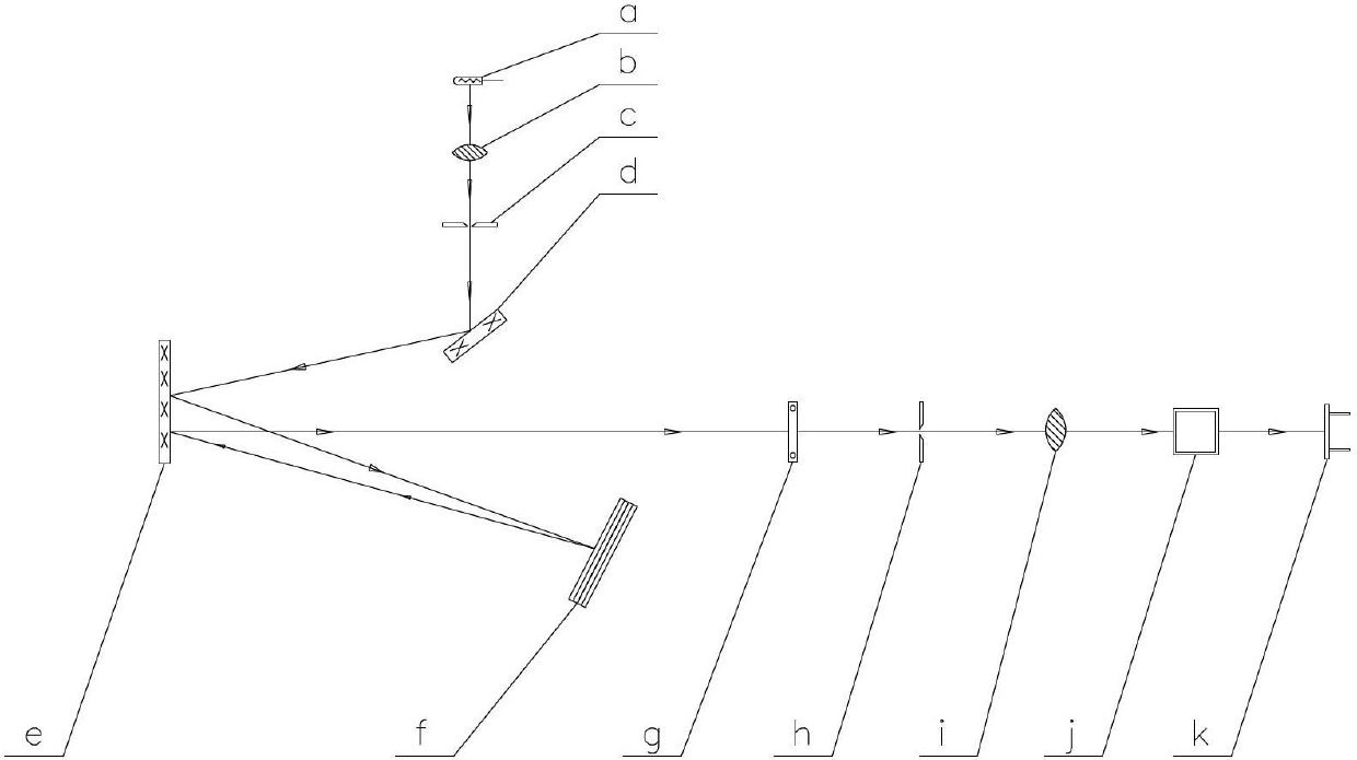
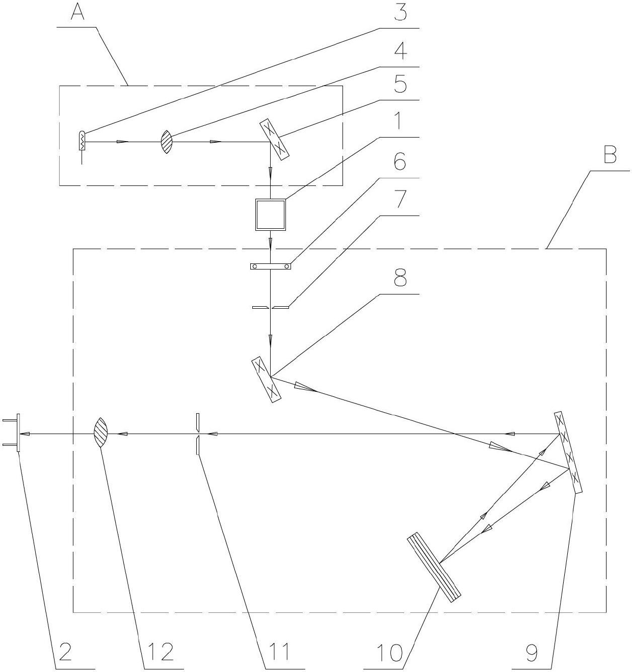
[0019] As attached figure 1 with 2 As shown, a spectrophotometer optical system designed by the present invention includes a front optical path A, a sample cell 1, a spectroscopic system B, and a photoelectric receiver 2, wherein the front optical path A is at the front end of the sample cell 1, including The light source 3, the light from the light source 3 shines on the first convex lens 4, the light comes out of the first convex lens 4 and then shines on the first reflector 5 at the focal position of the symmetrical side of the first convex lens 4 and the light source 3. The reflector 5 reflects into the sample cell 1 and then exits from the sample cell 1 into the spectroscopic system B. The spectroscopic system B includes a filter 6, a light entrance slit 7, a second mirror 8, a collimator 9, a grating 10, and a light exit narrow Slit 11, second convex lens 12, the...


PUM


Abstract

The invention relates to a spectrophotometer optical system and a special optical filter picking mechanism for the same. The spectrophotometer optical system comprises a front light path (A), a sample cell (1), an optical splitting system (B) and a photoelectric receiver (2), and is characterized in that the front light path (A) comprises a light source (3) on the front end of the sample cell (1), wherein the light of the light source (3) is transmitted onto a first convex lens (4), a first reflection mirror (5) is installed at the side of the first convex lens (4) to be symmetric to the light source (3), the first reflection mirror (5) is arranged on a focal point of the first convex lens (4), the light enters the optical splitting system (B) from the sample cell (1) after being reflected by the first reflection mirror (5) to the sample cell (1), and the light is emitted onto the photoelectric receiver (2) after being analyzed by the optical splitting system (B). According to a spectrophotometer manufactured by the optical system provided by the invention, the size of the spectrophotometer can be reduced, the cost is greatly reduced, and the mass popularization is realized.

Description

Technical field [0001] The invention relates to the technical field of spectroscopic instruments for material component analysis, in particular to an optical system of a spectrophotometer that analyzes material components by comparing the light intensity of a sample to be analyzed and a standard sample, and a special filter pick mechanism. Background technique [0002] It is well known that the visible spectrophotometer can perform qualitative and quantitative analysis of sample materials in the near ultraviolet-visible spectrum region. It is one of the commonly used spectral analysis instruments in physical and chemical laboratories. It uses an advanced blazed grating monochromator and has wavelength accuracy. High, good monochromaticity, low stray light, etc., adopts a microcomputer measurement system, τ-A conversion accuracy is high, and has automatic adjustment of 0% and 100%, concentration factor setting, concentration direct reading, and optional serial The data printer per...

Claims


Application Information

Patent Timeline
Patent Type & Authority Applications(China)
IPC IPC(8): G01N21/31G02B27/10G02B7/00
Inventor 周今伟周剑云陈晞钱宪明
Owner 上海现科分光仪器有限公司
Why Eureka
Try Eureka