
Gearbox fault diagnosing device, gearbox fault diagnosing method and gearbox

A fault diagnosis device and fault diagnosis technology, applied in the direction of transmission control, components with teeth, belts/chains/gears, etc., can solve the problems of time-consuming and labor-intensive inspection of hydraulic oil, large environmental dependence, indirect diagnosis, etc. , to achieve the effect of preventing abnormal work, ensuring normal operation and improving reliability

Active Publication Date: 2012-09-12
SANY HEAVY IND CO LTD (CN)
View PDF6 Cites 10 Cited by
  • Summary
  • Abstract
  • Description
  • Claims
  • Application Information

AI Technical Summary

Problems solved by technology

At present, the fault diagnosis of the gearbox is usually diagnosed by detecting and analyzing the gearbox temperature, the pressure of the pressure port or the oil of the hydraulic oil. These analysis methods are highly dependent on the environment and have poor reliability. Oil inspection is time-consuming and labor-intensive
Moreover, the implementation of these analysis checks is usually in the late stage of the fault, when the problem is already very serious, and the diagnosis is made in an indirect way, and the cause of the fault cannot be effectively analyzed in a targeted manner

Method used


Image

  • Gearbox fault diagnosing device, gearbox fault diagnosing method and gearbox
  • Gearbox fault diagnosing device, gearbox fault diagnosing method and gearbox
  • Gearbox fault diagnosing device, gearbox fault diagnosing method and gearbox

Examples


Embodiment Construction

[0022] In order to understand the above-mentioned purpose, features and advantages of the present invention more clearly, the present invention will be further described in detail below in conjunction with the accompanying drawings and specific embodiments. It should be noted that, in the case of no conflict, the embodiments of the present application and the features in the embodiments can be combined with each other.

[0023] In the following description, many specific details are set forth in order to fully understand the present invention. However, the present invention can also be implemented in other ways different from those described here. Therefore, the protection scope of the present invention is not limited by the specific details disclosed below. EXAMPLE LIMITATIONS.

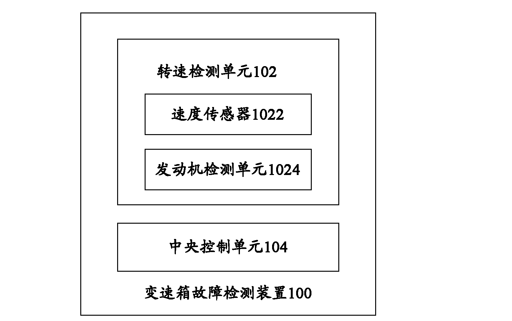
[0024] figure 1 It is a block diagram of a gearbox fault diagnosis device according to an embodiment of the present invention.

[0025] Such as figure 1As shown, the present invention provides a t...


PUM


Abstract

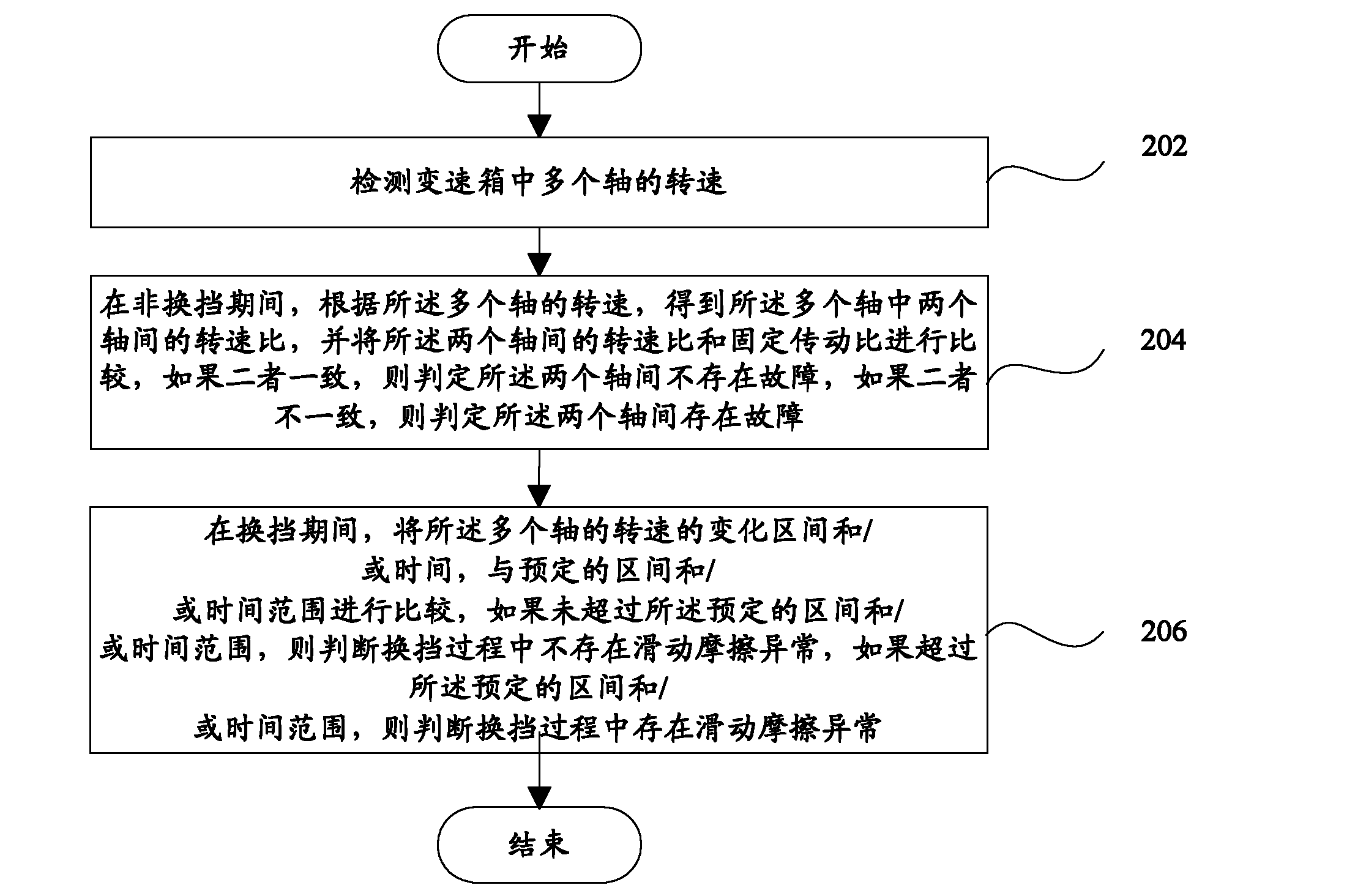
The invention provides a gearbox fault diagnosing device, a gearbox fault diagnosing method and a gearbox. The gearbox fault diagnosing device comprises a rotation speed detection unit and a central control unit; the rotation speed detection unit is used for detecting the rotation speeds of a plurality of shafts in the gearbox; the central control unit is used for obtaining the rotation speed ratio of two shafts in the shafts in non-shift process according to the rotation speeds of the shafts, and comparing the rotation speed ratio of the two shafts with a fixed transmission ratio, if the rotation speed ratio and the fixed transmission ratio are the same, the central control unit determines that no fault exists between the two shafts; if the rotation speed ratio and the fixed transmission ratio are different, the central control unit determines that a fault exists between the two shafts; and / or in the shift process, the central control unit is used for judging whether the change area of the rotation speed of the shafts and / or the time exceeds the preset area and / or time range or not, if not, the central control unit judges that no abnormal sliding friction exists in the shift process; if so, the central control unit judges that abnormal sliding friction exists in the shift process. With the adoption of the device, the method and the gearbox provided by the invention, whether a fault exists between any two shafts of the gearbox can be easily detected.

Description

technical field [0001] The invention relates to the field of construction machinery transmission, in particular to a gearbox fault diagnosis device, a gearbox fault diagnosis method and a gearbox. Background technique [0002] The gearbox is installed in the transmission system of construction machinery, mainly through hydraulic means, to control the engagement and disengagement of the multi-disc clutch under load, to connect different meshing relationship gear trains, so that the transmission ratio of the gearbox and the rotation of the output shaft The direction changes, thereby changing the vehicle's driving speed and direction (forward or backward). [0003] The gearbox is an important part of the power shift control system, and whether its working condition is normal has a direct relationship with the vehicle performance of construction machinery. At present, the fault diagnosis of the gearbox is usually diagnosed by detecting and analyzing the gearbox temperature, the...

Claims


Application Information

Patent Timeline
IPC IPC(8): F16H61/12
Inventor 李志勇马娇符溪
Owner SANY HEAVY IND CO LTD (CN)
Learn More