
Bar limiting mechanism for hot shearing machine

A technology of limiting mechanism and thermal shearing, applied in positioning devices, metal processing mechanical parts, clamping and other directions, can solve the problems of inconvenient cutting and circulation, affecting the operation of operators, etc., to achieve convenient transition operation, rapid switching, Simple and convenient operation and reliable results

Pending Publication Date: 2017-12-01
江苏礼德铝业有限公司
View PDF11 Cites 0 Cited by
  • Summary
  • Abstract
  • Description
  • Claims
  • Application Information

AI Technical Summary

Problems solved by technology

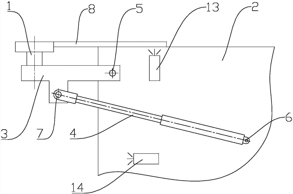
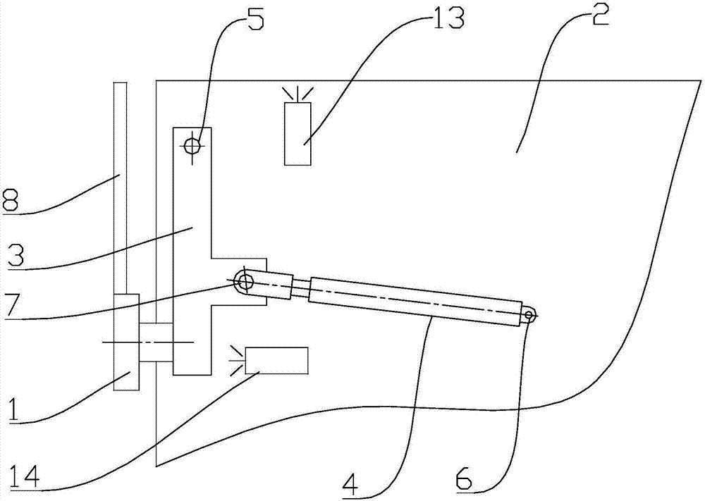
[0004] The technical problem to be solved by the present invention is: the limit mechanism used by the existing thermal shearing machine to cut the workpiece is a fixed structure, which causes inconvenient cutting and circulation and affects the operation of the operator. The present invention provides a rod for thermal shearing machine. Material limit mechanism to solve the above problems

Method used


Image

  • Bar limiting mechanism for hot shearing machine
  • Bar limiting mechanism for hot shearing machine
  • Bar limiting mechanism for hot shearing machine

Examples


Embodiment Construction

[0016] Embodiments of the present invention are described in detail below, examples of which are shown in the drawings, wherein the same or similar reference numerals designate the same or similar elements or elements having the same or similar functions throughout. The embodiments described below by referring to the figures are exemplary only for explaining the present invention and should not be construed as limiting the present invention. On the contrary, the embodiments of the present invention include all changes, modifications and equivalents coming within the spirit and scope of the appended claims.

[0017] In describing the present invention, it should be understood that the terms "center", "longitudinal", "transverse", "length", "width", "thickness", "upper", "lower", "front", " Back", "Left", "Right", "Vertical", "Horizontal", "Top", "Bottom", "Inner", "Outer", "Axial", "Radial", "Circumferential", etc. The indicated orientation or positional relationship is based ...


PUM


Abstract

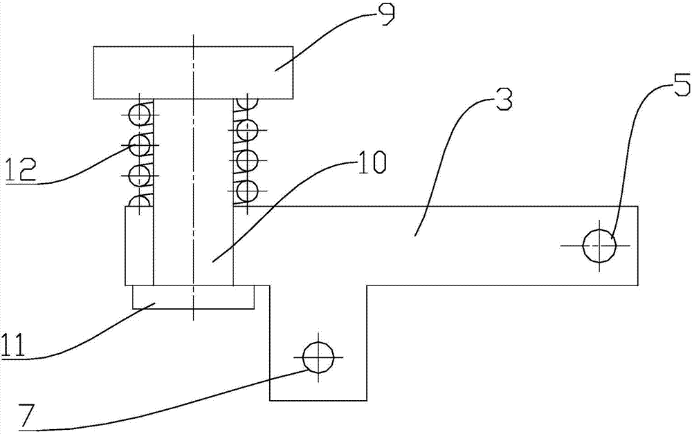
The invention provides a bar limiting mechanism for a hot shearing machine. The bar limiting mechanism comprises a limit stopping block, a fixed support, a movable support and an oil cylinder. The movable support is arranged at the left side of the fixed support. A first hinged point is arranged between the right end of the movable support and the fixed support. The limit stopping block is arranged at the left end of the movable support. A second hinged point is arranged between the right end of the oil cylinder and the fixed support. A third hinged point is arranged at the left end of the oil cylinder and located in the middle of the movable support. A piston rod of the oil cylinder is telescopic to drive the movable support to rotate around the first hinged point. The movable limit stopping block is arranged and can be stretched out when positioning is required and be removed when positioning is completed, space is given to material cutting, transfer operation of operators is facilitated, and the structure is fast to switch and easy, convenient and reliable to operate.

Description

technical field [0001] The invention relates to a limiting mechanism, in particular to a bar limiting mechanism for a heat shearing machine. Background technique [0002] Aluminum processing uses plastic processing methods to process aluminum ingots into materials. The main methods are rolling, extrusion, stretching and forging. When processing aluminum profiles, it is usually necessary to equip special conveying equipment to assist in the finishing and packaging of strip-shaped finished profiles. [0003] It is usually necessary to use a thermal shearing machine to cut off the bar. When the thermal shearing machine is cut off, the length of the cut material is controlled by a limit mechanism. Usually, the limit mechanism is a fixed structure in the prior art. When the limit work is completed The rear limit mechanism will interfere with the transition transportation of the cut material, which will bring great inconvenience to the operator. Contents of the invention [00...

Claims


Application Information

Patent Timeline
Patent Type & Authority Applications(China)
IPC IPC(8): B23Q3/18
CPCB23Q3/18
Inventor 王平马在平裴瑞丰张洪波吉广健陈峰顾洁云顾慧丽
Owner 江苏礼德铝业有限公司
Learn More