Control circuit and method for a ripple regulator system
A technology for controlling circuits and regulators, which is applied in the direction of adjusting electrical variables, control/regulation systems, pulse duration/width modulation, etc., and can solve problems such as small ripples
- Summary
- Abstract
- Description
- Claims
- Application Information
AI Technical Summary
Problems solved by technology
Method used
Image
Examples
Embodiment Construction
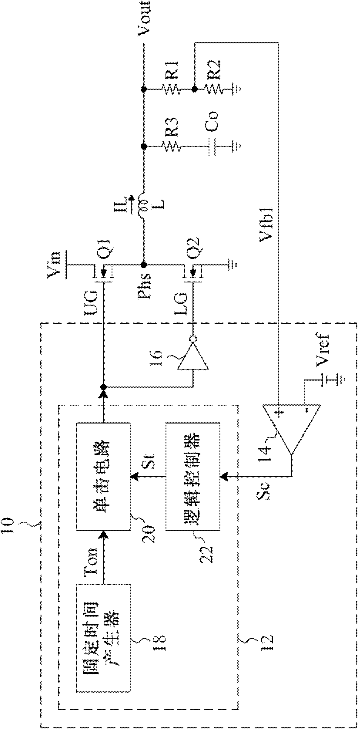
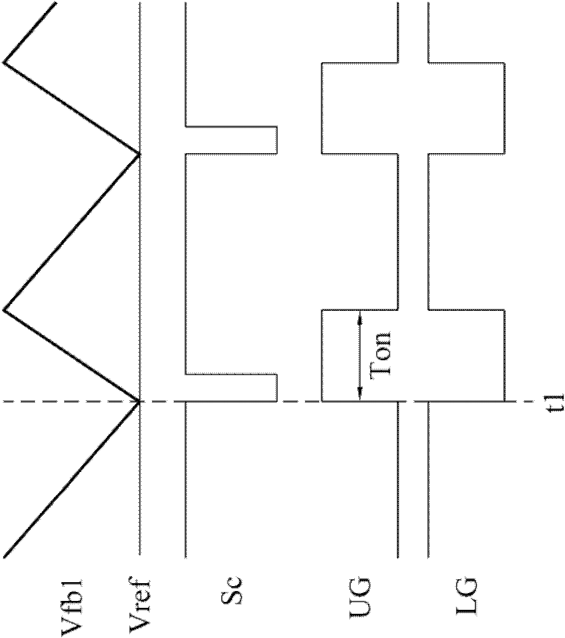
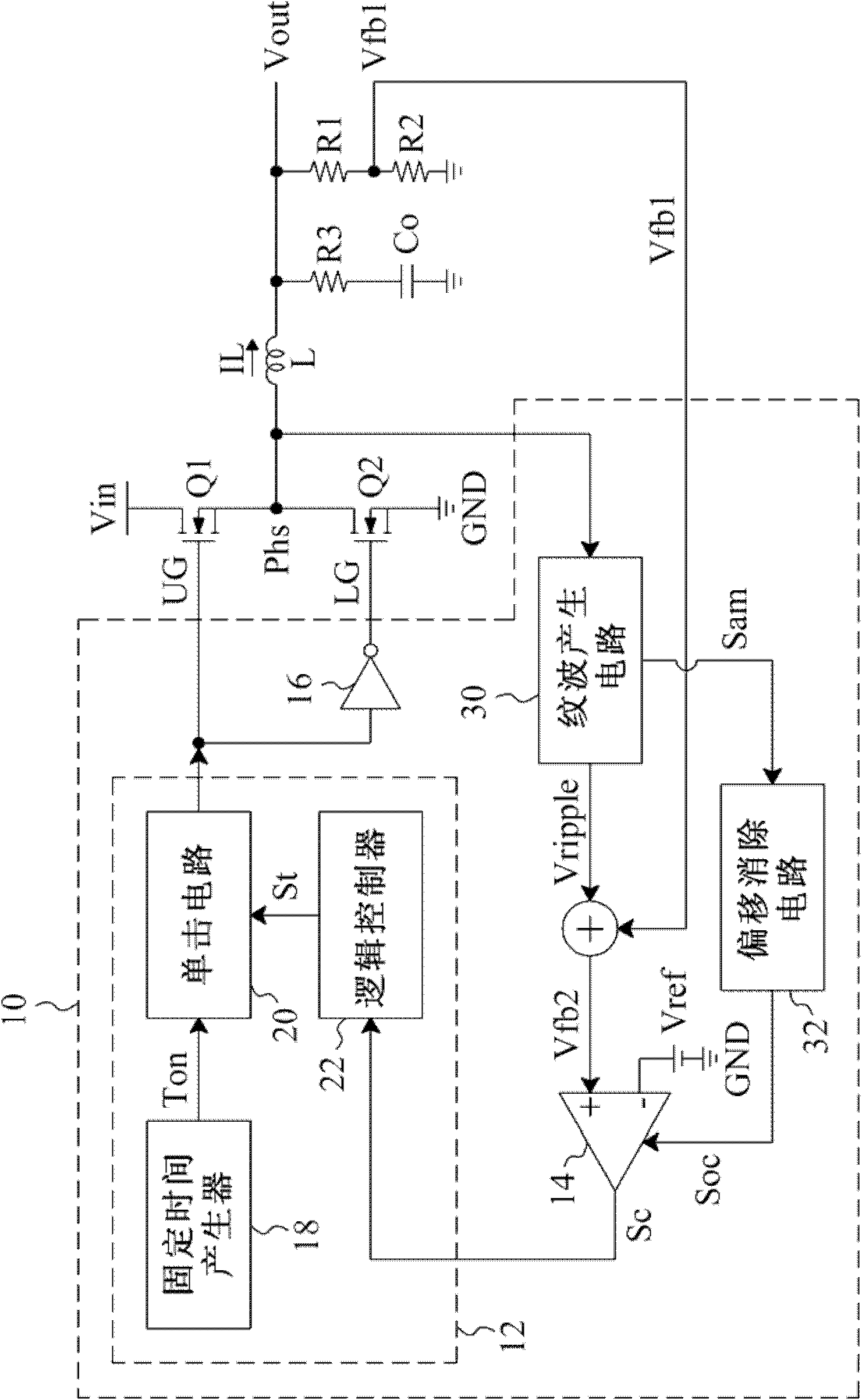
[0032] image 3 so figure 1 The embodiment based on the design of the circuit, wherein the equivalent series resistance R3 of the output voltage stabilizing capacitor Co is very small, so the ripple of the feedback voltage Vfb1 is very small, which can be regarded as a DC signal, such as Figure 4 The waveform 36 is shown. exist image 3 of the control circuit 10, in addition to figure 1 In addition to the PWM controller 12 , the error comparator 14 and the inverter 16 , it also includes a ripple generating circuit 30 and an offset canceling circuit 32 . The ripple generating circuit 30 generates a ripple signal Vripple synchronous with the inductor current IL and in phase with the voltage of the phase node Phs to the positive input terminal of the error comparator 14, and the ripple signal Vripple is superimposed on the feedback voltage Vfb1 to generate a large ripple wave feedback voltage Vfb2, such as Figure 4 As shown in the waveform 34 of , the problem of loop insta...
PUM
 Abstract
Description
Claims
Application Information
 - R&D
- Intellectual Property
- Life Sciences
- Materials
- Tech Scout
- Unparalleled Data Quality
- Higher Quality Content
- 60% Fewer Hallucinations
Browse by: Latest US Patents, China's latest patents, Technical Efficacy Thesaurus, Application Domain, Technology Topic, Popular Technical Reports.
© 2025 PatSnap. All rights reserved.Legal|Privacy policy|Modern Slavery Act Transparency Statement|Sitemap|About US| Contact US: help@patsnap.com


