Efficiency testing device and method for automobile clutch separating system

A technology of efficiency test and separation system, which is applied in the field of efficiency test device of automobile clutch separation system, which can solve problems such as unfavorable load efficiency and stroke efficiency of clutch separation system, influence on automobile power transmission, NVH performance, driver control comfort, error, etc. , to achieve the effect of improving NVH performance

Inactive Publication Date: 2015-05-13
SAIC-GM-WULING AUTOMOBILE CO LTD
View PDF7 Cites 0 Cited by
  • Summary
  • Abstract
  • Description
  • Claims
  • Application Information

AI Technical Summary

Problems solved by technology

However, the clutch separation system actually produced at present often has a large gap between the pedal force and the pedal stroke of the original design; moreover, there are certain errors in the installation process of the car; especially, the current clutch separation system In the design check, only the total load efficiency and stroke efficiency experience value, there is no simple measurement method to obtain the load efficiency and stroke efficiency from the clutch pedal to the clutch cylinder
These are very detrimental to the improvement of the load efficiency and stroke efficiency of the clutch separation system, seriously affecting the power transmission, NVH performance and driver's control comfort of the car

Method used


Image

  • Efficiency testing device and method for automobile clutch separating system
  • Efficiency testing device and method for automobile clutch separating system
  • Efficiency testing device and method for automobile clutch separating system

Examples


Embodiment Construction

[0029] Below in conjunction with accompanying drawing, preferred embodiment of the present invention is described in further detail:

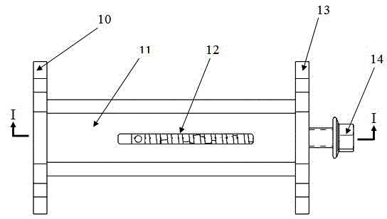
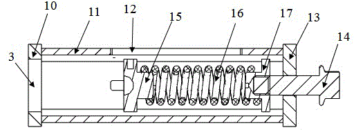
[0030] Such as figure 1 and figure 2 As shown, a kind of efficiency testing device of automobile clutch disengagement system, comprises the first connection plate 10, support tube 11 and the second connection plate 13 that are connected in sequence; and the second spring seat 17; the first spring seat 15, the spring 16 are connected with the second spring seat 17 in turn; the outer wall of the support tube 11 is also provided with a scale groove 12, and the length of the scale groove 12 is greater than or equal to that of the spring 16, the compression of the spring 15 can be fully seen through the scale groove 12; the first connection plate 10 is provided with a through hole 3, and the through hole 3 communicates with the support tube 11. In practical applications, in order to obtain the pressure and displacement of the spring 15 at any tim...


PUM


Abstract

The invention provides an efficiency testing device and an efficiency testing method for an auto clutch separating system. The efficiency testing device comprises a first connecting plate (10), a supporting pipe (11) and a second connecting plate (13) which are sequentially connected; a first spring seat (15), a spring (16) and a second spring seat (17) are arranged inside the supporting pipe (11); and the first spring seat (15) and the spring (16) are sequentially connected with the second spring seat (17). The force at a pedal and the displacement of the pedal can be obtained by connecting the efficiency testing device with a clutch slave cylinder, testing the stress and the displacement applied at a push rod of the slave cylinder and further connecting a pedal dynamometer to the clutch pedal; through the comparison between the forces and the displacements at the two places, the load efficiency and the stroke efficiency from the clutch pedal to the clutch slave cylinder can be obtained, further the reason for heavy clutch pedal can be diagnosed, the clutch pedal is checked and adjusted, and the auto NVH (noise vibration and harshness) performance and the control comfort degree of a driver can be improved greatly.

Description

technical field [0001] The invention relates to a test technology of a clutch separation system, in particular to an efficiency test device and method of an automobile clutch separation system. Background technique [0002] Clutch release system, as the actuator for operating the clutch in the car, includes pedals, ropes or hydraulic mechanisms, clutch release arms, clutch release shafts and release bearings, etc., which have an important impact on the power transmission and NVH performance of the vehicle, especially It is the separation force of the clutch pedal, which seriously affects the driver's control comfort. [0003] Clutch release system, as the actuator for operating the clutch in the car, includes pedals, ropes or hydraulic mechanisms, clutch release arms, clutch release shafts and release bearings, etc., which have an important impact on the power transmission and NVH performance of the vehicle, especially It is the separation force of the clutch pedal, which s...

Claims


Application Information

Patent Timeline
Patent Type & Authority Patents(China)
IPC IPC(8): G01M13/02
Inventor 吕兆平赖玉龙覃辉翔
Owner SAIC-GM-WULING AUTOMOBILE CO LTD
Why Eureka
Try Eureka