
Composite bushing type water spraying desuperheater

A technology of spraying water for desuperheating and composite casing, which is applied in the control of superheat temperature, steam superheating, steam generation, etc., can solve the problems of cantilever vibration of nozzle device, crack of desuperheater liner, fracture of nozzle device, etc., to avoid Leakage defects and limitations of low temperature and low pressure use, ease of manufacturing and assembly, and enhanced recoil effect

Active Publication Date: 2014-05-14
SHANGHAI BOILER WORKS
View PDF3 Cites 0 Cited by
  • Summary
  • Abstract
  • Description
  • Claims
  • Application Information

AI Technical Summary

Problems solved by technology

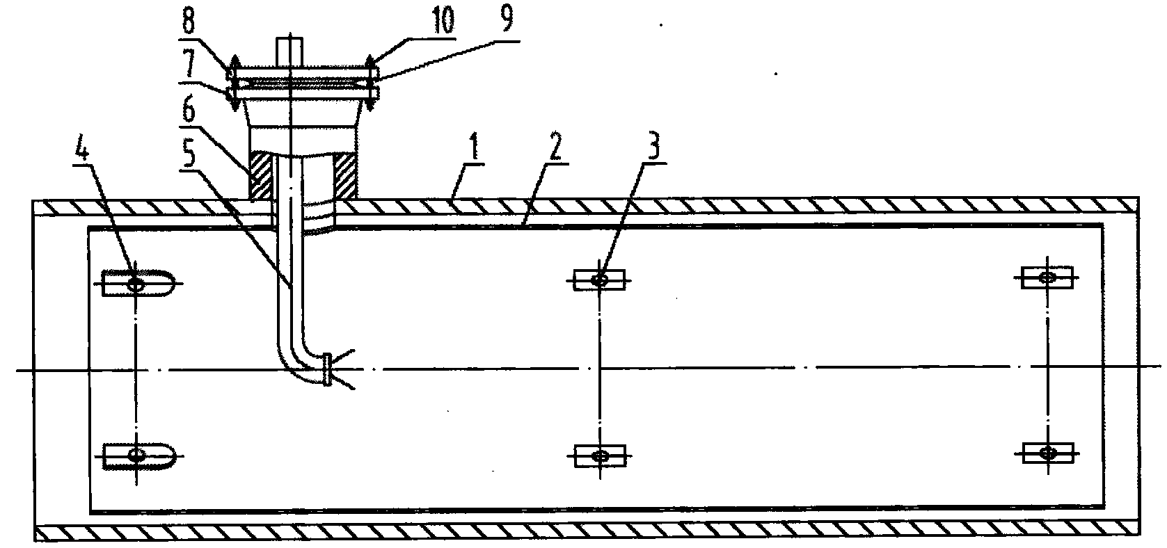
[0004] The traditional single pipe seat with flange type water spray desuperheater has the following disadvantages: the nozzle device will vibrate cantilever during operation, which will easily cause the nozzle device to break, and the desuperheating water will be sprayed from the fracture, and the desuperheater bushing and cylinder will be damaged due to temperature difference. Stress forms cracks, and if the broken nozzle tip flows into the hot side tube with the air flow, it will cause the tube to burst
The flange connection pair consisting of flange 7, flange cover 8, stud bolt 9 and nut 10 is prone to leakage when the desuperheater is running, so it is not suitable for use in the water spray desuperheater under high temperature and high pressure operation

Method used


Image

  • Composite bushing type water spraying desuperheater
  • Composite bushing type water spraying desuperheater
  • Composite bushing type water spraying desuperheater

Examples


Embodiment Construction

[0018] In order to make the present invention more comprehensible, a preferred embodiment is described in detail below with accompanying drawings.

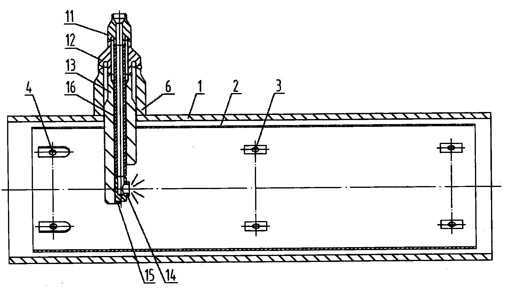
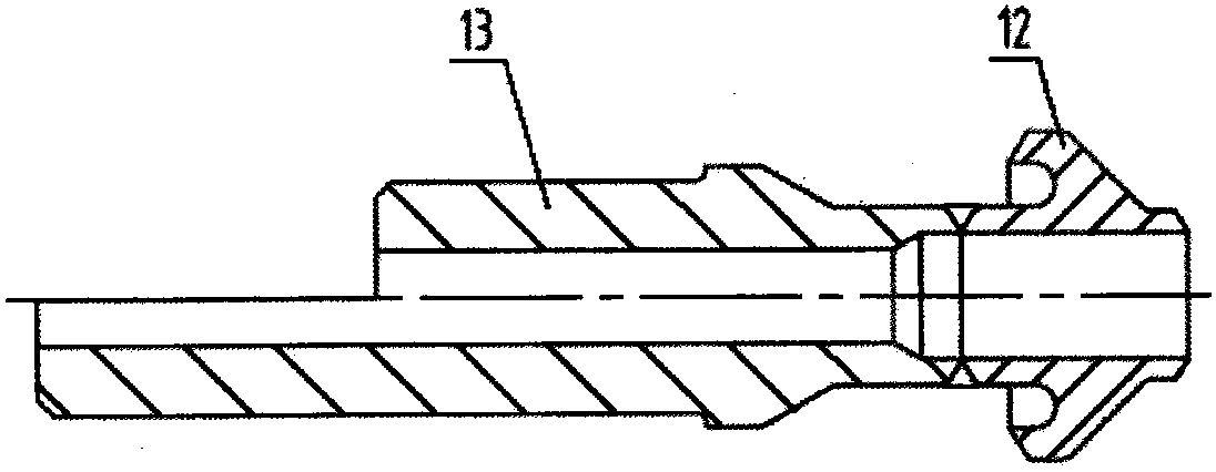
[0019] figure 2 It is a structural schematic diagram of a composite casing type water spray desuperheater provided by the present invention. The composite casing type water spray desuperheater is composed of a cylinder body 1, an inner bushing 2, a support bolt 3, and a fixing bolt 4 , the main body pipe seat 6, the inner layer of nozzle 11 of the composite pipe seat, the outer layer of nozzle 12 of the composite pipe seat, the nozzle strengthening protection pipe 13, the fixed support block 15 and the nozzle pipe 16.

[0020] The cylinder body 1 has an inner bushing 2 built in, and the inner bushing 2 is fixed by fixing bolts 4 and supported and positioned by support bolts 3 . One end of the inner bushing 2 is fixed in the axial direction of the desuperheater by the fixing bolt 4, and the other end of the inner bushing 2 is a f...


PUM


Abstract

The invention provides a composite bushing type water spraying desuperheater which comprises a cylinder body and an inner bushing arranged inside the cylinder body, wherein a body pipe seat is arranged above one end of the cylinder body. The composite bushing type water spraying desuperheater is characterized in that a spray nozzle strengthened protection pipe is coaxially arranged inside the body pipe seat; an outer-layer pipe mouth of the composite seat pipe is connected with the spray nozzle strengthened protection pipe; the lower end of an inner-layer pipe mouth of the composite pipe seat is arranged inside the upper end of the outer-layer pipe mouth of the composite pipe seat; the upper end of a spray nozzle pipe which is coaxially arranged inside the spray nozzle strengthened protection pipe is connected with the inner-layer pipe mouth of the composite pipe seat; and a fixed support block is arranged below the spray nozzle pipe. According to the composite bushing type water spraying desuperheater disclosed by the invention, the defects in the prior art are overcome; due to the adoption of the sealed composite bushing seat and the spray nozzle strengthened protection pipe, the application range of the composite bushing type water spraying desuperheater is widened and the safety and the reliability of the operation process of the composite bushing type water spraying desuperheater are enhanced. The composite bushing type water spraying desuperheater has the advantages of simple structure, convenience in manufacture and assembly and convenience in maintenance.

Description

technical field [0001] The invention relates to a composite casing type water spray desuperheater, which is used in the reheater and superheater system of a boiler in a power station, and belongs to the technical field of water spray desuperheater devices. Background technique [0002] The desuperheater is an important device used to adjust the steam temperature of the steam boiler. In a thermal power plant, if there is no desuperheater, the temperature of the steam at the outlet of the boiler cannot be controlled within the rated range, which will damage the boiler steam turbine and other components or cause major accidents. The regulation of steam temperature is divided into two categories: flue gas side regulation and steam side regulation. The spray desuperheater is the main means to adjust the steam temperature on the steam side. [0003] The traditional single pipe seat with flanged water spray desuperheater device such as figure 1 As shown, a thin-walled inner line...

Claims


Application Information

Patent Timeline
Patent Type & Authority Patents(China)
IPC IPC(8): F22G5/12
Inventor 周曙光王瑞娟叶伟民
Owner SHANGHAI BOILER WORKS
Learn More