
Meter structure for motorcycle

A technology for motorized two-wheeled vehicles and instruments, which is applied to instruments, vehicle parts, bicycle accessories, etc., and can solve the problems of fading lighting effect and luminous effect of light guide pointers, and achieves excellent style, improved luminous effect, and improved design The effect of precision

Active Publication Date: 2012-08-29
HONDA MOTOR CO LTD +1
View PDF9 Cites 0 Cited by
  • Summary
  • Abstract
  • Description
  • Claims
  • Application Information

AI Technical Summary

Problems solved by technology

[0004] However, in the above-mentioned existing instrument structure, since the light-emitting diode is located at a position separated from the light-guiding pointer, the lighting effect on the light-guiding pointer becomes weak, especially in motorized two-wheeled vehicles, because there is no A device that blocks the light from the outside, so that the faint glow becomes even weaker

Method used


Image

  • Meter structure for motorcycle
  • Meter structure for motorcycle
  • Meter structure for motorcycle

Examples


Embodiment Construction

[0046] Hereinafter, embodiments of the present invention will be described with reference to the drawings.

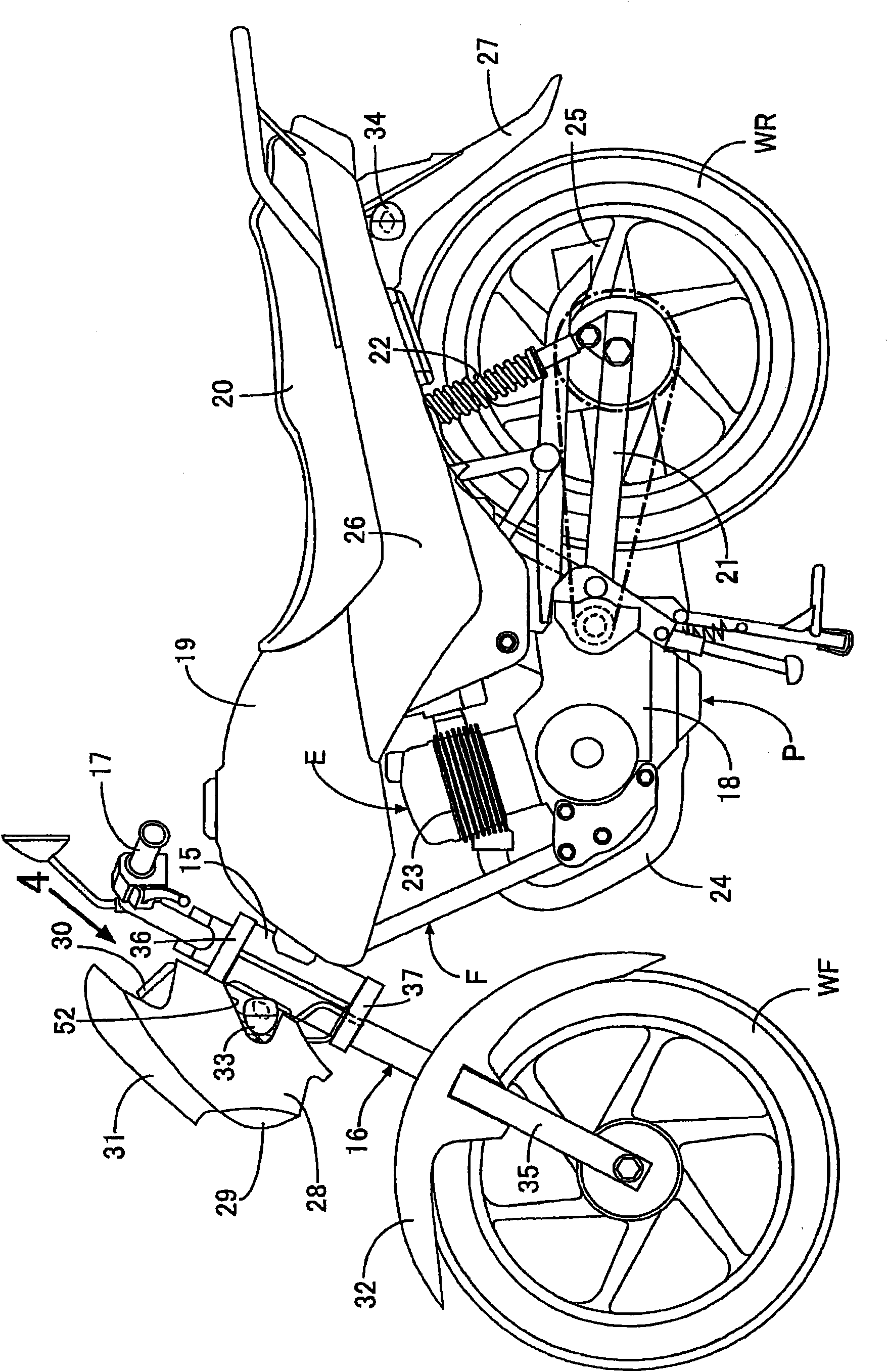
[0047] refer to Figure 1 to Figure 11 , to describe the embodiment of the present invention, first, in figure 1 In this motorcycle, a front fork 16 and a steering handle 17 are steerably supported on a head pipe 15 provided at the front end of the body frame F of the motorcycle. The front fork 16 pivotally supports the front wheel WF. At the rear, an engine main body 18 of an engine E is mounted on the body frame F, and a power unit P is constituted by the engine E and a transmission (not shown) built in the engine main body 18 . Above the power unit P, a fuel tank 19 is mounted on a body frame F, and a passenger seat 20 arranged behind the fuel tank 19 is supported by the rear portion of the body frame F. As shown in FIG.

[0048] Behind the power unit P, the front end of the swing arm 21 is supported by the body frame F so that the swing arm 21 can swing, and the r...


PUM


Abstract

The invention provides a meter structure for a motorcycle. To increase light emitting effect by efficiently guiding light from a light emitting diode to a light guide indicator in a meter structure for motorcycle in which a movement having a turning shaft disposed at an opening provided at a scale indicator plate and a circuit board are fixed to a back side of the scale indicator plate, an indication part of the light guide indicator connected to the turning shaft in a manner not allowing relative rotation is disposed at a surface side of the scale indicator plate, and the light emitting diode for causing the light guide indicator to emit light is mounted on a surface of the circuit board at a part facing the opening. The circuit board (98) is against a back side of the scale indicator plate and is fixed to the scale indicator plate (80) and the light emitting diode (102) is adjacent to a rotary shaft (93) and is mounted on a surface of the circuit board (98).

Description

technical field [0001] The present invention relates to a meter structure for a motorcycle, wherein a mechanism having a rotating shaft arranged in an opening provided on a scale display plate and a circuit board are fixed on the back side of the scale display plate, and are connected to the rotating shaft. The indication part of the light guide pointer whose axis is not relatively rotatable is arranged on the surface side of the scale display panel, and on the surface of the circuit board is mounted a Light-emitting diodes. Background technique [0002] In Patent Document 1, the following structure is known: a circuit board is fixedly arranged on the back side of the scale display panel, and there is a gap between the circuit board and the scale display panel, and a light-emitting diode for making the light guide pointer emit light is installed on the surface of the circuit board. [0003] Patent Document 1: Japanese Patent Laid-Open No. 2008-8818 [0004] But, in above-...

Claims


Application Information

Patent Timeline
IPC IPC(8): B60K35/00B62J99/00G01D13/04G01D11/28G01P1/08
Inventor 周越顾倍倍
Owner HONDA MOTOR CO LTD
Learn More