
Deashing device and method for waste incineration boiler and biomass boiler

A biomass boiler and waste incineration technology, applied in the boiler field, can solve the problems of high investment cost, poor economy, difficult to remove slagging, etc., and achieve the effects of lower tube wall temperature, good fatigue resistance, and convenient deformation

Active Publication Date: 2012-08-22
ZHEJIANG FUCHUNJIANG ENVIRONMENTAL THERMOELECTRIC CO LTD +1
View PDF4 Cites 10 Cited by
  • Summary
  • Abstract
  • Description
  • Claims
  • Application Information

AI Technical Summary

Problems solved by technology

[0003] At present, how to effectively clean the ash on the convective heating surface of the waste incineration boiler and the biomass boiler is still in the stage of continuous exploration. There are not many ways to reduce the ash on the convective heating surface. There are three main methods: one is to stop the boiler after serious slagging Manually remove slag from the furnace, this method has poor economy, high labor intensity, and incomplete slag removal; the second is to use a soot blower to blow soot on the heating surface during the operation of the boiler. The generated slagging is difficult to remove, and the equipment investment cost is high, and the structure of the soot blower is complicated; the third is to add additives such as dolomite or limestone to the fuel, which can reduce the formation of alkali metal compound sulfate and achieve the purpose of reducing the ash on the heated area. However, this method is generally effective in the actual operation process
In waste incineration boilers and biomass boilers, the metal hose tubes arranged in the convection flue are used to intercept the ash deposits, and the ash deposits deposited on the surface of the metal hoses are removed by deforming the metal hoses, thereby There is no report on the ash removal method and device for reducing the deposition of ash-forming substances in the flue gas on the subsequent heating surface

Method used


Image

  • Deashing device and method for waste incineration boiler and biomass boiler
  • Deashing device and method for waste incineration boiler and biomass boiler
  • Deashing device and method for waste incineration boiler and biomass boiler

Examples


Embodiment

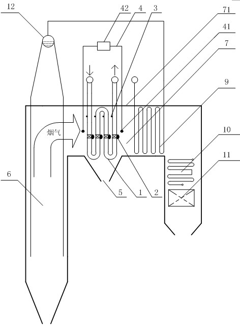
[0034] The convection tube bundle in the horizontal flue exit of a 75t / h waste incineration boiler furnace in a power plant is made of φ51mm×4 steel pipes, arranged in 42 rows horizontally and 13 rows vertically, with a horizontal pitch of 140mm and a vertical pitch of 150mm. The average temperature of the flue gas is 750°C. The device is used to remove ash deposits; considering the size of the horizontal flue at the furnace outlet and the characteristics of the combustion flue gas, the metal hose is made of φ38mm high-temperature resistant pipes, arranged in 4 rows in a staggered manner, with a horizontal intercept of 65mm and a longitudinal intercept of 150mm. The hose is arranged 300mm in front of the first group of convection tube bundles; the push rod is made of φ70mm 06Cr25Ni20 stainless steel tube, and the temperature measuring device is a K-type thermocouple, which is arranged on the windward side of the metal hose tube row and the appropriate position on the push rod su...


PUM

PropertyMeasurementUnit
Outer diameteraaaaaaaaaa

Abstract

The invention provides a deashing device and method for a waste incineration boiler and a biomass boiler. The deashing device is characterized by comprising a metal hose (1), a push rod (2), a temperature measuring device (3), a differential pressure measuring device (4) and an ash discharge port (5); and a horizontal flue (7) at the exit of a boiler furnace (6) is surrounded by a horizontal flue furnace wall (71) and is hollow. The method comprises the following steps: flue gas leaves the furnace (6) and flows through the metal hose (1) arranged in the horizontal flue (7) so that ash deposition in the flue gas can be blocked by the metal hose (1); when the drop changes of the temperature and the resistance measured by the temperature measuring device (3) and the differential pressure measuring device (4) exceed threshold values, the push rod (2) starts to do reciprocating motion and drives the metal hose (1) to deform, so that the ash deposition deposited on the surface of the metal hose (1) can fall off from the surface due to the deformation and can be discharged from the ash discharge port (5). The deashing device provided by the invention has a simple structure; in addition, the deashing device and method have the advantages of high deashing efficiency, low cost and wide application range.

Description

Technical field [0001] The present invention involves a waste incineration boiler and biomass boiler clearance method and device, which belongs to the field of boiler technology. Background technique [0002] With the continuous advancement of my country's urbanization process and the continuous improvement of people's living standards, in many areas, domestic waste problems have gradually become an important factor in restricting urban development and environmental improvement. It is becoming more and more widely used in my country.After the "Kyoto Protocol" takes effect, biomass can become a hot spot in the energy field due to the advantages of nearly zero carbon dioxide emissions.Direct power generation of biomass is one of the most convenient and efficient biomass can be used, and it has developed rapidly in my country.However, in the process of incineration of garbage and biomass, ash crickets caused by ash in the fuel are commonly existed on the heating surfaces of the burn...

Claims


Application Information

Patent Timeline
IPC IPC(8): F23J1/06F23J3/02
Inventor 张忠梅陈晓平楼军唐智金孝祥刘道银盛洪产梁财赵长遂
Owner ZHEJIANG FUCHUNJIANG ENVIRONMENTAL THERMOELECTRIC CO LTD
Learn More