Vacuum bonding method of anticorrosive fluoroplastic lining

A technology of anti-corrosion fluoroplastics and bonding method, which is applied in the field of vacuum bonding of anti-corrosion fluoroplastic linings, can solve the problems that the overall seamless structure cannot be realized, the lining layer is prone to collapse, and the anti-corrosion lining fails, etc., achieving low production costs, Prevents drum breakage and prolongs service life

Active Publication Date: 2014-02-19
ZHEJIANG DONGFU PLASTIC SCI & TECH
View PDF7 Cites 0 Cited by
  • Summary
  • Abstract
  • Description
  • Claims
  • Application Information

AI Technical Summary

Problems solved by technology

This lining method is to use an integral seamless fusible fluoroplastic as the container lining to overcome the problem that the quality of the spliced ​​structure lining is difficult to guarantee, but the manufacturing cost of this lining method is high, and only the cylindrical part of the lining can be made. Therefore, the two ends of the lining container often need to be welded and spliced, and the overall seamless structure cannot be realized. Therefore, when working under high temperature or negative pressure conditions, the lining layer is also prone to collapse, bulge and even rupture, which directly leads to Anti-corrosion lining failure and other technical problems

Method used


Image

  • Vacuum bonding method of anticorrosive fluoroplastic lining
  • Vacuum bonding method of anticorrosive fluoroplastic lining

Examples


Embodiment

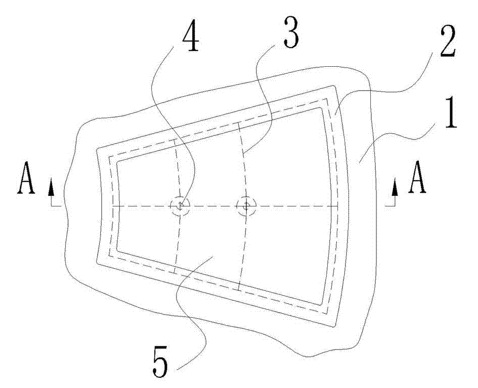
[0035] 2) Pre-cut a number of anti-corrosion fluoroplastic plates 5, which are cut from PTFE activated plates, and require anti-corrosion fluoroplastic plates 5 to match the shape and size of the inner cavity of the container 1 when spliced ​​on the inner wall of the container 1 consistent;

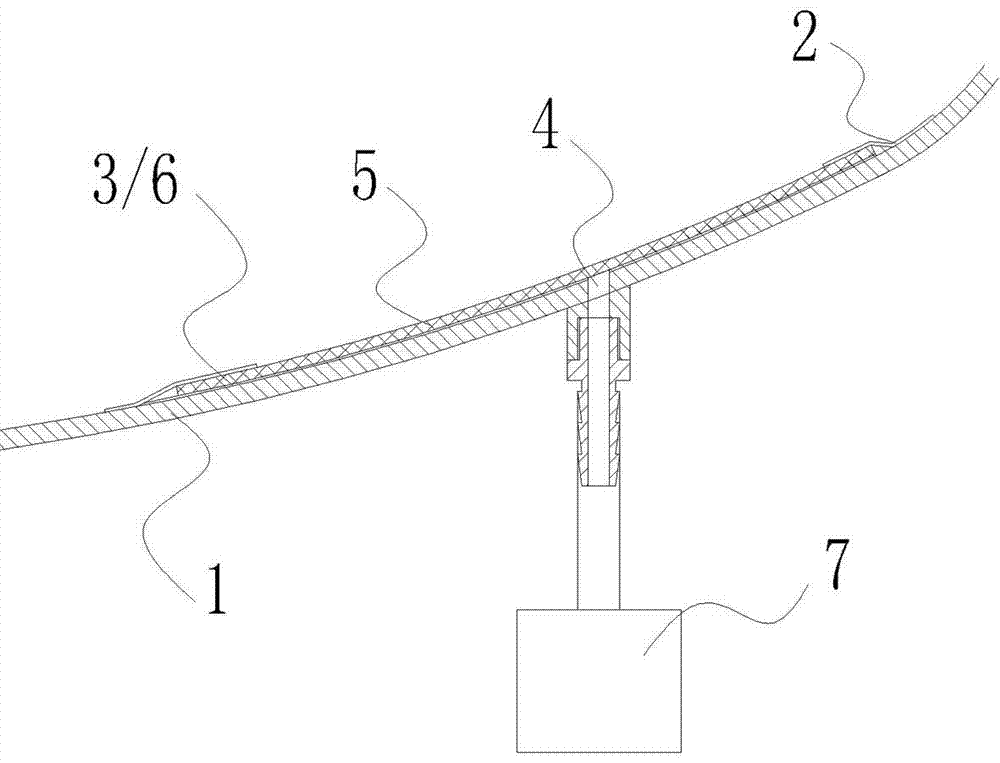
[0036] 3) Open a number of through holes 4 on the wall of the lining container 1 corresponding to each anti-corrosion fluoroplastic plate 5, such as figure 2 As shown, the through hole 4 is connected with the vacuum pump 7 outside the lining container 1 through a joint;

[0037] 4) Paint the polymer adhesive 6 on the surface of the inner cavity of the lining container 1 and the bonding surface of the anti-corrosion fluoroplastic plate 5 respectively. The polymer adhesive 6 is epoxy glue, and paint repeatedly 3 times to make the The thickness of the epoxy adhesive layer reaches 0.4 mm, and when repainting, ensure that the epoxy adhesive layer painted last time is completely dry (based on ...


PUM

PropertyMeasurementUnit
thicknessaaaaaaaaaa
coating thicknessaaaaaaaaaa

Abstract

The invention discloses a lining method of chemical equipment and provides a vacuum bonding method of an anticorrosive fluoroplastic lining, solving the technical problem in the prior art that the lining layers are liable to collapse, expand, fracture and the like under the working condition of high temperature or negative pressure, thus causing failure of the anticorrosive lining. The method has the following advantages: the manufacture cost is low; and the lining is tightly lined in a container through vacuum absorption, thus improving the high temperature and negative pressure resistance of the equipment. The process roughly comprises the following steps: cutting a plurality of anticorrosive fluoroplastic boards which can be fully stuck in the container flatwise, painting polymer binders on the anticorrosive fluoroplastic boards and the inner wall of the container respectively, putting a plurality of fiber ropes which are arranged in a cross manner on the pasting surfaces of the anticorrosive fluoroplastic boards after the anticorrosive fluoroplastic boards are aired and sticking the anticorrosive fluoroplastic boards on the inner wall of the container flatwise, arranging through holes on the container wall corresponding to the cross points of the fiber ropes and communicating the through holes with vacuum equipment, then carrying out vacuumizing after sealing the peripheries of the anticorrosive fluoroplastic boards firmly with adhesive tapes and primarily vulcanizing the additionally corresponding container areas, carrying out thermo-fusion welding on the joints after all the anticorrosive fluoroplastic boards are pasted and carrying out steam pressurizing after double leakage detection to complete secondary vulcanization.

Description

technical field [0001] The invention relates to a lining method of chemical equipment, in particular to a vacuum bonding method of the anticorrosion fluoroplastic lining tightly lining the container by vacuum adsorption, which improves the high temperature resistance and negative pressure resistance performance of the equipment. Background technique [0002] The existing chemical equipment is lined with anti-corrosion fluoroplastics. The traditional methods mainly include equal pressure PTFE, winding PTFE, lap welding of PTFE plates, etc., but the above-mentioned lining methods have a common disadvantage, that is, the anti-corrosion fluoroplastic lining layer There is a gap between it and the inner wall of the container, so it is collectively called the loose lining method. However, when the loose lining method is used for lining, if it is under high temperature or negative pressure conditions, the lining layer will often collapse, bulge or even crack, which will directly lea...

Claims


Application Information

Patent Timeline
Patent Type & Authority Patents(China)
IPC IPC(8): B29C63/30
Inventor 何正纲顾秋林
Owner ZHEJIANG DONGFU PLASTIC SCI & TECH
Why Eureka
Try Eureka