Manufacturing method of rubber mandrel for automotive part
A technology of auto parts and manufacturing methods, applied in the field of auto parts, to achieve the effects of long service life, low cost and increased connection length
- Summary
- Abstract
- Description
- Claims
- Application Information
AI Technical Summary
Problems solved by technology
Method used
Image
Examples
Embodiment 1
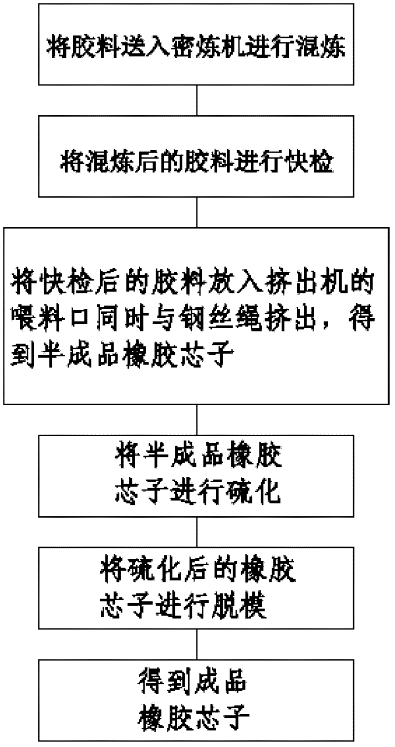
[0027] like figure 1 Shown, the manufacture method of the rubber core that a kind of auto parts of the present invention is used, manufacture method comprises the steps:
[0028] Step 1, the rubber material is sent into the internal mixer for mixing;
[0029] In step 2, the rubber compound after mixing is subjected to a quick inspection test;
[0030] Step 3, put the rubber material in step 2 into the feeding port of the extruder and extrude it with the steel wire rope at the same time to obtain a semi-finished rubber core;
[0031] Step 4, put the semi-finished rubber core of step 3 into a vulcanization tank for vulcanization;
[0032] Step 5, demoulding the vulcanized rubber core;
[0033] Step six, get the finished rubber core.
[0034] The internal mixer described in step 1 is a machine that is equipped with a pair of rotors of specific shape and rotates relatively, and intermittently masticates and kneads polymer materials in a closed state with adjustable temperature...
Embodiment 2
[0044] The manufacturing method comprises the steps of:
[0045] Step 1, the rubber material is sent into the internal mixer for mixing;
[0046] In step 2, the rubber compound after mixing is subjected to a quick inspection test;
[0047] Step 3, put the rubber material in step 2 into the feeding port of the extruder and extrude it with the steel wire rope at the same time to obtain a semi-finished rubber core;
[0048] Step 4, put the semi-finished rubber core of step 3 into a vulcanization tank for vulcanization;
[0049] Step 5, demoulding the vulcanized rubber core;
[0050] Step six, get the finished rubber core.
[0051]The internal mixer described in step 1 is a machine that is equipped with a pair of rotors of specific shape and rotates relatively, and intermittently masticates and kneads polymer materials in a closed state with adjustable temperature and pressure. It is composed of mixing chamber, rotor, rotor sealing device, feeding and pressing device, unloadin...
Embodiment 3
[0061] The manufacturing method comprises the steps of:
[0062] Step 1, the rubber material is sent into the internal mixer for mixing;
[0063] In step 2, the rubber compound after mixing is subjected to a quick inspection test;
[0064] Step 3, put the rubber material in step 2 into the feeding port of the extruder and extrude it with the steel wire rope at the same time to obtain a semi-finished rubber core;
[0065] Step 4, put the semi-finished rubber core of step 3 into a vulcanization tank for vulcanization;
[0066] Step 5, demoulding the vulcanized rubber core;
[0067] Step six, get the finished rubber core.
[0068] The internal mixer described in step 1 is a machine that is equipped with a pair of rotors of specific shape and rotates relatively, and intermittently masticates and kneads polymer materials in a closed state with adjustable temperature and pressure. It is composed of mixing chamber, rotor, rotor sealing device, feeding and pressing device, unloadi...
PUM
 Abstract
Description
Claims
Application Information
 - R&D Engineer
- R&D Manager
- IP Professional
- Industry Leading Data Capabilities
- Powerful AI technology
- Patent DNA Extraction
Browse by: Latest US Patents, China's latest patents, Technical Efficacy Thesaurus, Application Domain, Technology Topic, Popular Technical Reports.
© 2024 PatSnap. All rights reserved.Legal|Privacy policy|Modern Slavery Act Transparency Statement|Sitemap|About US| Contact US: help@patsnap.com


