
Resolver digital converter

A technology of resolver and digital converter, applied in the direction of converting sensor output, instruments, measuring devices, etc., can solve the problems of low detection accuracy, inability to offset error amplitude error, etc., and achieve the effect of improving reproducibility and fast processing

Active Publication Date: 2014-11-05
HONDA MOTOR CO LTD
View PDF9 Cites 0 Cited by
  • Summary
  • Abstract
  • Description
  • Claims
  • Application Information

AI Technical Summary

Problems solved by technology

In addition, in these maximum and minimum values ​​with low detection accuracy, there arises a problem that the offset error and the amplitude error cannot be appropriately corrected while ensuring the desired accuracy.

Method used


Image

  • Resolver digital converter
  • Resolver digital converter
  • Resolver digital converter

Examples


Embodiment Construction

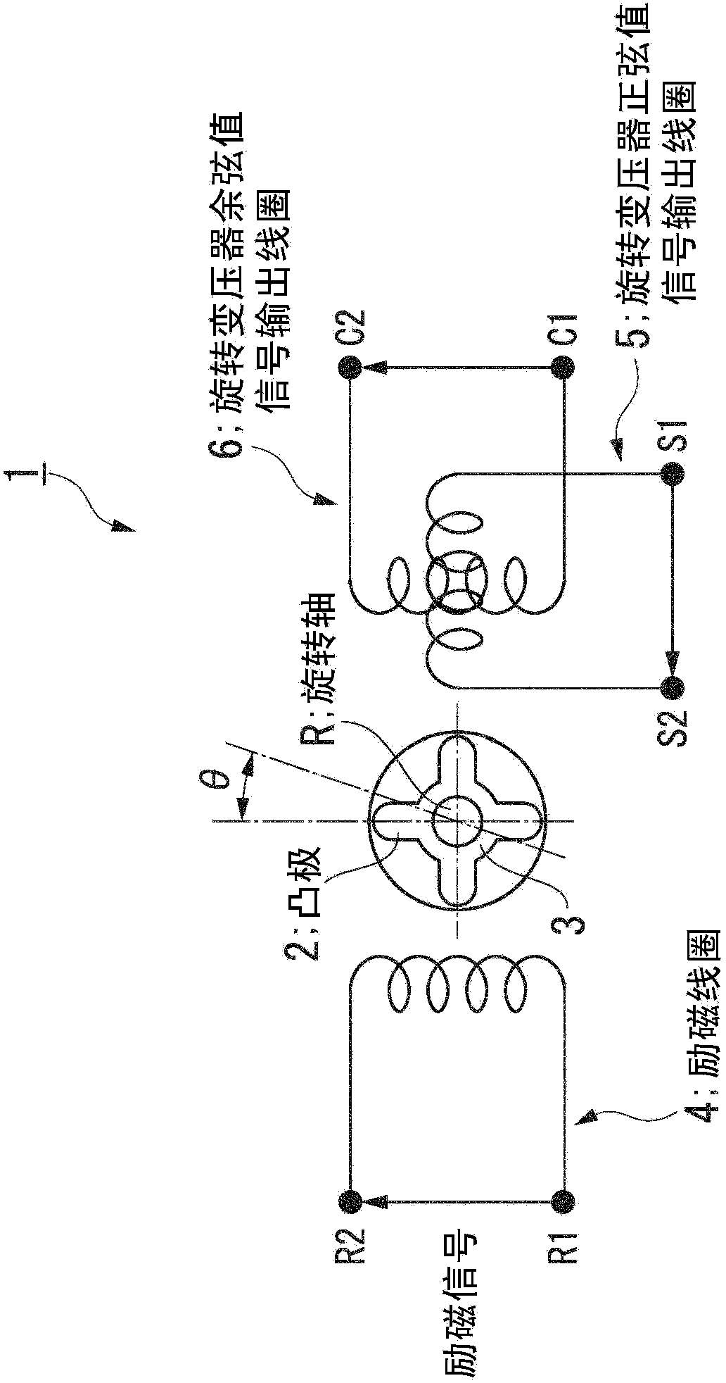
[0034] Hereinafter, an embodiment of the resolver-to-digital converter of the present invention will be described with reference to the drawings.

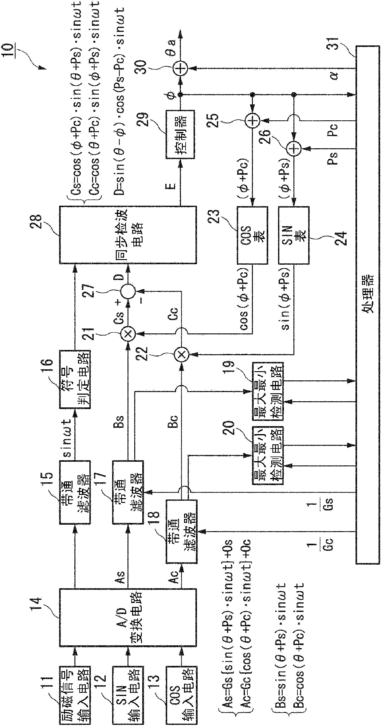
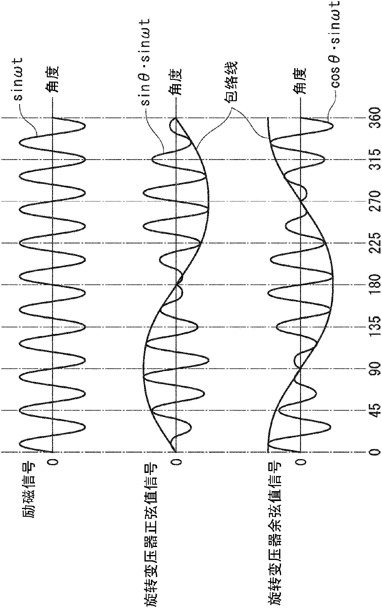
[0035] The resolver-to-digital converter 10 of this embodiment converts, for example, a detection signal output from a resolver 1 of a 1-phase excitation-2-phase output type or the like into a digital angle signal. The resolver-to-digital converter 10 is for example figure 1 As shown, it is configured to include: an excitation signal input circuit 11, a resolver sine value signal (SIN) input circuit 12, a resolver cosine value signal (COS) input circuit 13, an analog-to-digital (A / D) conversion circuit (analog-digital Converter) 14, band-pass filter for excitation signal (band-pass processing unit) 15, sign determination circuit 16, first and second band-pass filter for detection signal (band-pass processing unit, correction unit) 17, 18. First and second maximum and minimum detection circuits 19, 20, first and second multiplicati...


PUM


Abstract

This resolver digital converter (10) comprises bandpass processing units each of which is disposed between a converting unit and a multiplying unit and that performs the processing in a period, which is shorter than the sampling period of the analog-to-digital converter, and that passes only the signals of a given band. The gains of the digital signals, before being input to the multiplying unit, are corrected by use of a gain correction value established from the maximum and minimum values of the digital signals having passed through the bandpass processing unit.

Description

technical field [0001] The present invention relates to resolver-to-digital converters. [0002] this application claims priority based on Japanese Patent Application No. 2009-276416 for which it applied to Japan on December 4, 2009, and uses the content here. Background technique [0003] Conventionally, for example, in the error correction method of an absolute position detection device described in Patent Document 1, the offset included in the analog output voltage is corrected by using digital values ​​obtained by A / D converting the analog output voltages of sine waves and cosine waves. error, amplitude error, phase error. [0004] In addition, conventionally, for example, in the resolver correction method described in Patent Document 2, the digital output obtained by A / D converting the analog value of the output signal output from the resolver is used to correct the Offset error, amplitude error. [0005] prior art literature [0006] patent documents [0007] Pate...

Claims


Application Information

Patent Timeline
Patent Type & Authority Patents(China)
IPC IPC(8): G01D5/20
CPCG01D5/20G01D5/2046
Inventor 高桥尚良
Owner HONDA MOTOR CO LTD
Learn More