
Relay double break dynamic driving circuit with frequency detection function

A drive circuit and frequency detection technology, applied in relays, circuits, electrical components, etc., can solve problems such as hidden dangers of railway safe operation, poor anti-interference ability, and incorrect driving of relays, and achieve the effect of improving anti-interference ability and improving safety.

Inactive Publication Date: 2012-08-15
SHENYANG RAILWAY SIGNAL
View PDF4 Cites 0 Cited by
  • Summary
  • Abstract
  • Description
  • Claims
  • Application Information

AI Technical Summary

Problems solved by technology

The existing dynamic drive circuit is realized by capacitor charging and discharging, and there are factors such as poor anti-interference ability. Therefore, when driving dynamically, considering the actual on-site operating environment of railway signals, strong interference will cause the relay to be mis-driven, which will affect the safe operation of the railway. bring hidden danger

Method used


Image

  • Relay double break dynamic driving circuit with frequency detection function
  • Relay double break dynamic driving circuit with frequency detection function

Examples


Embodiment Construction

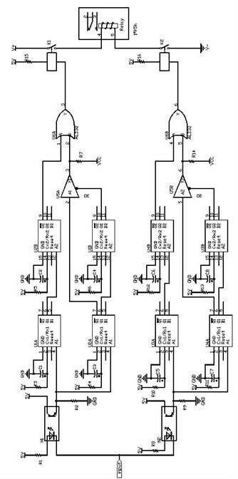
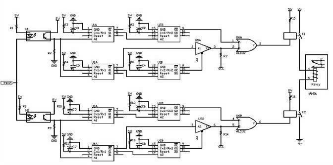
[0010] The input drive pulse is divided into two paths through the optocouplers N1 and N2 to trigger their respective post-stage circuits respectively. U1A, U2A, U3A, and U4A are monostable trigger circuits, and realize the frequency discrimination function by selecting their own R and C. The outputs of N1 and N2 are respectively used as the input of the first U1A and U2A, and the second U3A and U4A, and the upper limit frequency detection of the first and second driving pulses is completed through the set R3, R10, C1 and C5; Set R4, R11 and C3, C7 to complete the lower limit frequency detection of the first and second drive pulses. The outputs of U1A and U3A are respectively used as the trigger signal input of U2B and U4B, and the first and second level conversions are completed through the set R5, R12 and C2, C6 to obtain the required continuous level, which is used as the first OR gate U6A and U6B One input; the Q output of U2A, U4A is used as the trigger signal input of U...


PUM


Abstract

The invention provides a relay double break dynamic driving circuit with a frequency detection function, mainly solving the problems that the conventional driving circuit adopts a capacitance charge-discharge manner, has factors of poor antijamming capability and the like, so that a hidden trouble can be produced to safe operation of a railway. The relay double break dynamic driving circuit has key points that the relay double break dynamic driving circuit takes a monostable trigger as a core component, a frequency range of a driving pulse can be identified, and only a driving signal within an allowable frequency range can drive a relay to act. The relay double break dynamic driving circuit disclosed by the invention has the beneficial effects that double ends of a relay excitation coil are controlled at the same time, and frequency detection on a dynamic signal is realized by adopting a frequency discriminating circuit, and thus false operation of the relay can be guaranteed not to be caused at a non-working frequency, and antijamming capability is improved.

Description

technical field [0001] The invention relates to a relay dynamic drive circuit in a railway signal system, in particular to a relay double-break dynamic drive circuit with frequency detection. Background technique [0002] As the most important execution device in the field of signal control, the relay completes the execution process by driving the signal. The existing dynamic drive circuit is realized by capacitor charging and discharging, and there are factors such as poor anti-interference ability. Therefore, when driving dynamically, considering the actual on-site operating environment of railway signals, strong interference will cause the relay to be mis-driven, which will affect the safe operation of the railway. bring hidden dangers. Contents of the invention [0003] In order to solve the above-mentioned technical problems, the object of the present invention is to provide a relay double-break dynamic drive circuit with frequency detection with a monostable trigger...

Claims


Application Information

Patent Timeline
IPC IPC(8): H01H47/00
Inventor 蔡小勇宋超雷杨孙林林王昀王英奇王润隆孙瑛田海燕王进忠王洋
Owner SHENYANG RAILWAY SIGNAL
Learn More