
Collection device for collecting cells after laser microdissection, method and system thereof

A technology of laser microdissection and collection device, which is applied in sampling devices, preparation of samples for testing, etc., can solve the problems of reduced cell collection efficiency, difficult laser cutting, and easy loss of charge, so as to avoid contamination of samples, facilitate collection, High Compatibility Effects

Active Publication Date: 2012-08-08
MOTIC CHINA GRP CO LTD
View PDF8 Cites 16 Cited by
  • Summary
  • Abstract
  • Description
  • Claims
  • Application Information

AI Technical Summary

Problems solved by technology

However, this method has the following disadvantages. First: it can only be applied to polyimide films, and it is a polyimide film with negative charges in advance. Materials that meet this requirement are not easy to find in the market.
Second: Because it is difficult for the industry to produce polyimide films with a thickness of less than 2 microns, and thicker films are difficult to cut by laser or leave burnt marks on the edge of the cutting line after cutting
Third: Difficulty spreading negatively charged polyimide films on microscope slides
Fourth, the negatively charged polyimide film is prone to loss of charge during storage, which reduces the efficiency of cell collection
Fifth, it is difficult to find a positively charged collection material (agar is not charged). Even if it is found, the positively charged collection material is easy to lose as it is aged

Method used


Image

  • Collection device for collecting cells after laser microdissection, method and system thereof
  • Collection device for collecting cells after laser microdissection, method and system thereof
  • Collection device for collecting cells after laser microdissection, method and system thereof

Examples


Embodiment Construction

[0041] In order to make the technical problems, technical solutions and beneficial effects to be solved by the present invention clearer and clearer, the present invention will be further described in detail below in conjunction with the accompanying drawings and embodiments. It should be understood that the specific embodiments described here are only used to explain the present invention, not to limit the present invention.

[0042] Collecting device embodiment one

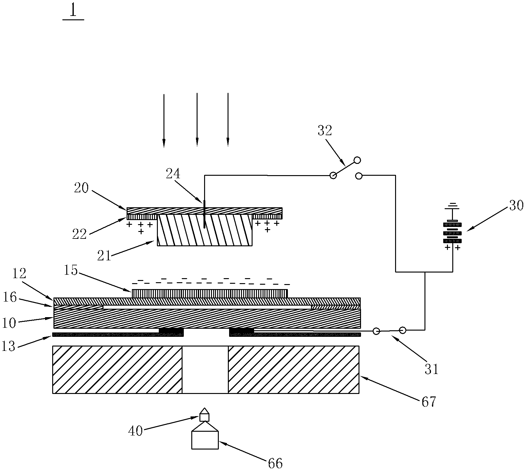
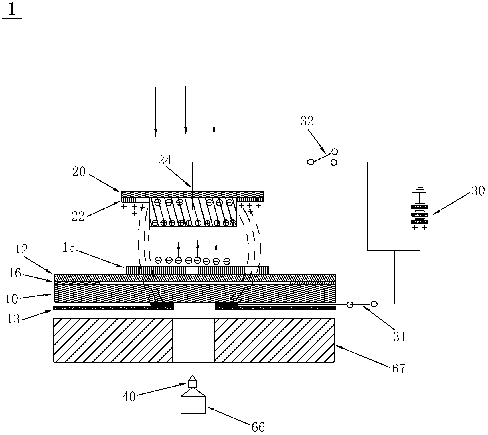
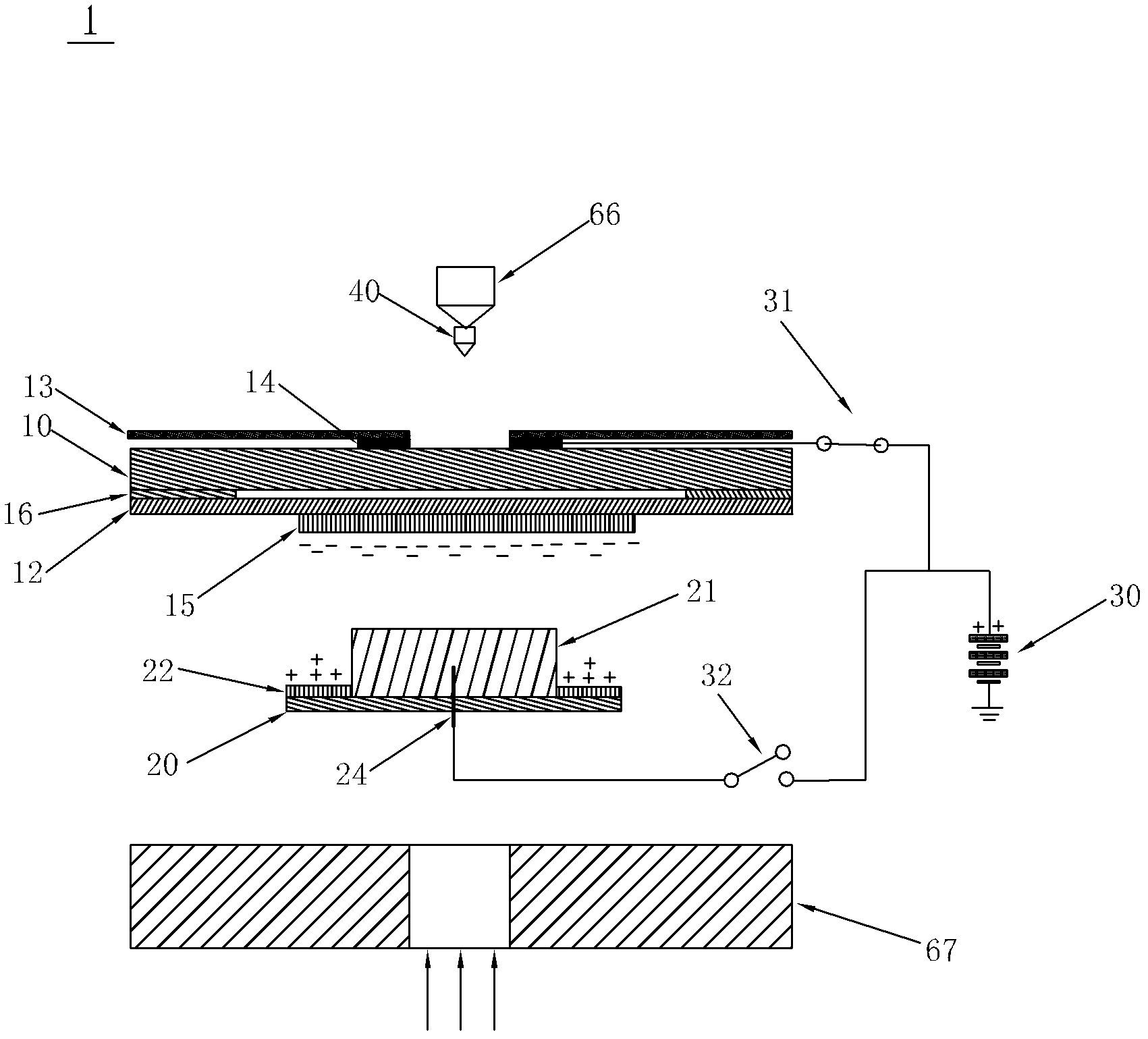
[0043] Such as figure 1 As shown, it shows a schematic diagram of the application of the collecting device for collecting cells after laser microdissection according to the present invention to an inverted laser microdissection system. The so-called inversion means that the cut cell tissue sample 15 and the transparent film layer 12 wrapping it move in the opposite direction of the gravity direction and are received by the sample collector 20 shown in the figure. Therefore, the cell tissue sample 15 is arranged...


PUM

PropertyMeasurementUnit
Thicknessaaaaaaaaaa
Thicknessaaaaaaaaaa

Abstract

The invention discloses a collection device for collecting cells after laser microdisssection, a method and a system thereof. The device provided by the invention comprises a sample carrier, two sides of which are respectively provided with a transparent film layer and an insulating layer, wherein the transparent film layer fits with the sample carrier and is equipped with cell tissue samples, and a first electrode is disposed between the insulating layer and the sample carrier; a sample collector which is filled with a cell adhesion material for the adhesion of cell tissues and is also provided with a light-sensitive material for photoelectric reaction after laser irradiation; and a power supply device, the positive electrode of which forms break-make stations with the first electrode through a first switch. By the above scheme, the disadvantage that the cell tissue samples during the collection process are polluted and that requirements on materials of the sample carrier and the sample collector are high, carried static charges are inconvenient to preserve and the collection efficiency is poor in the prior art is avoided. According to the cell collection device and the method thereof, functions are stable, and cell tissue samples will not be damaged.

Description

technical field [0001] The invention relates to a collection device, method and system for collecting cells after laser microdissection. Background technique [0002] In life science research, it is necessary to conduct gene and protein research on a specific cell (group) in a tissue. The laser micro-cell dissection device or system is a high-end equipment developed to meet such needs, which can separate a specific or characteristic cell (group) from a variety of tissues, thereby avoiding the need for experimental Specimens are contaminated by other cells, bacteria, or other impurities, making the analysis of genes and proteins more accurate and specific. The core technology that distinguishes various laser micro-cell dissection systems is the different collection methods or devices for non-polluting collection of cut cells. [0003] U.S. Patents US 7807108B2, US 6907798B2, etc. disclose cell collection devices, which are placed directly below the sample, and the cells (cl...

Claims


Application Information

Patent Timeline
IPC IPC(8): G01N1/28G01N1/04
Inventor 易定容
Owner MOTIC CHINA GRP CO LTD
Learn More