
200KW non-transferred arc plasma generator and arc-striking method

A plasma generator, non-transfer arc technology, applied in the direction of plasma, electrical components, etc., can solve the problems of unsuitability for industrialized large-scale production and application, short electrode life, small application range, etc., to improve arc voltage and arc stability. Uniform, wide-ranging effect

Active Publication Date: 2012-08-01
CHENGDU JINCHUANGLI SCI & TECH
View PDF10 Cites 11 Cited by
  • Summary
  • Abstract
  • Description
  • Claims
  • Application Information

AI Technical Summary

Problems solved by technology

[0004] The 200KW non-transferred arc plasma generator and arc striking method provided by the present invention are to solve the problem of large loss, low efficiency, short electrode life, small application range and unsuitability for industrialized large-scale production of existing low-power (below 100KW) plasma generators. and application issues

Method used


Image

  • 200KW non-transferred arc plasma generator and arc-striking method
  • 200KW non-transferred arc plasma generator and arc-striking method

Examples


Embodiment 200

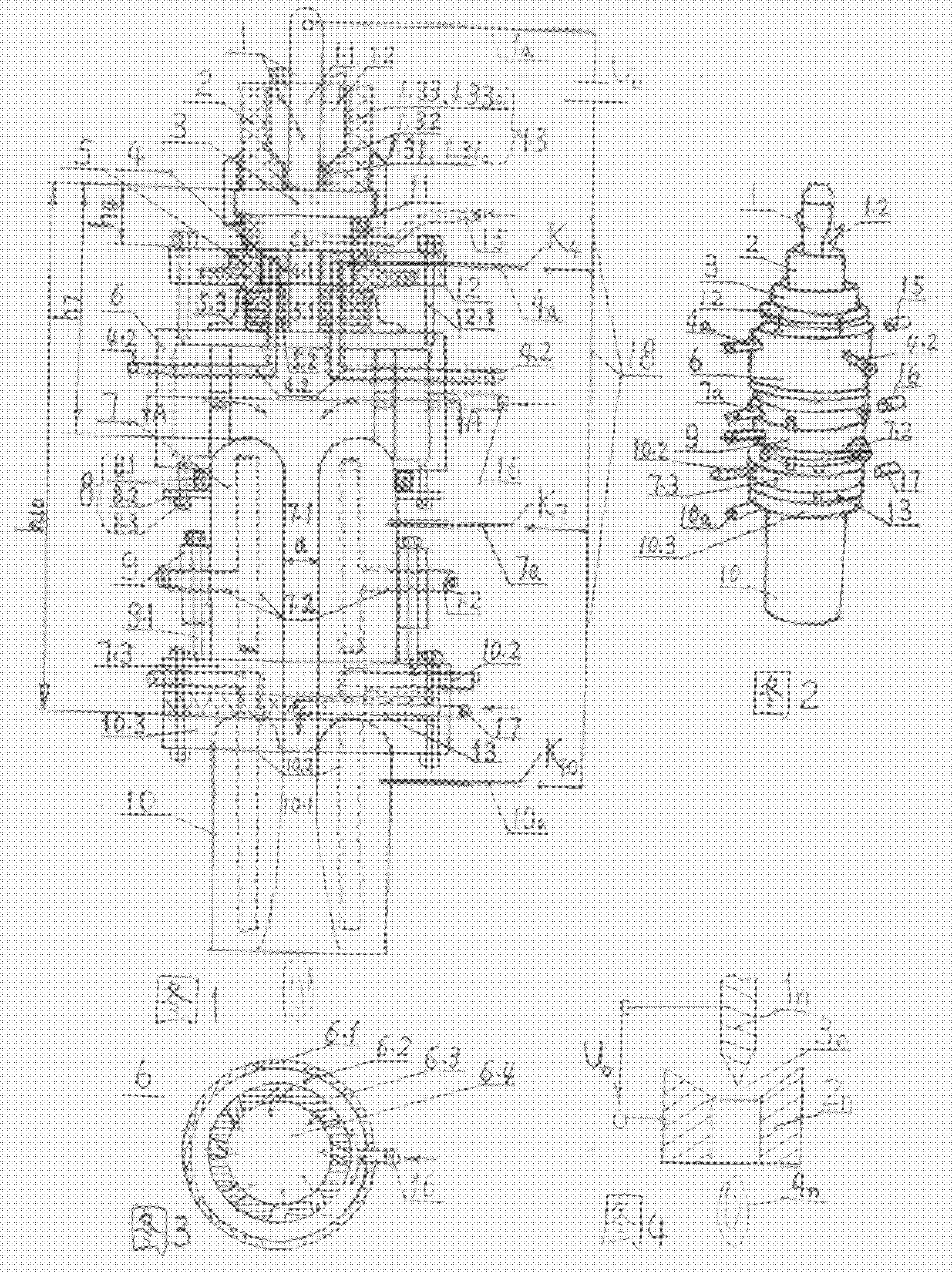
[0017] The 200KW non-transferred arc plasma generator of this embodiment is composed as follows:

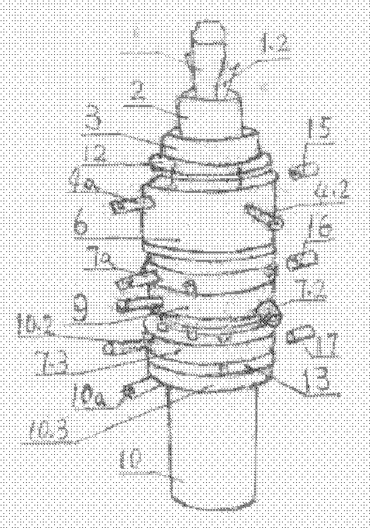
[0018] 1) General layout: see figure 1, From the arc generation to the ejection direction, the cathode 1, the insulating cylinder 2 around the cathode, the gap 3, the small anode 4 and the adjustable insulating seat 5 supporting the small anode, and the main gas ring that introduces the main gas from the outside to the center hole are arranged in sequence. 6, two anodes 7, the seal between the outer upper part of the two anodes and the main gas ring 8, the adjusting nut 9 of the outer circle of the two anodes and the large anode 10 with a trumpet spout at the lowermost end.

[0019] 2) Each electrode structure: see figure 1, The cathode 1 is a solid red copper electrode 1.1, the outer ring of the cathode is a stainless steel cylinder 1.3, and the interlayer between the solid red copper electrode 1.1 and the stainless steel cylinder 1.3 is a cooling water channel 1.2. The cold...


PUM


Abstract

Disclosed are a 200KW non-transferred arc plasma generator and an arc-striking method. A negative pole and an insulating sleeve, a clearance, a small positive pole and an adjustable insulating seat, a main gas ring, a second positive pole, an outside seal, an adjusting nut and a big positive pole are arranged sequentially along the injecting direction. The negative pole is of solid red copper, an outer ring of the negative pole is a stainless steel sleeve, and a cooling waterway is formed between the negative pole and the stainless steel sleeve. Each positive pole is of red copper with a center hole and a cooling waterway, a threaded junk ring and a special-shaped flange which can be adjustably connected at an axial direction are arranged outside each positive pole. Inert gases serving as assistant gases are ventilated to the top of the small positive pole; and main gases and protection gases are screwed in the second positive pole and the top of the big positive. The negative pole of the direct current power is connected with the negative pole of the plasma generator; the positive pole of the direct current power is connected with three positive poles of the plasma generator, and each positive pole is provided with an arc-transferring switch. Multiple positive poles are used for increasing the arc pressure, so that the power can be reached to 200KW. The main gases and protection gases are screwed in to produce stable and uniform arcs. Water-cooling is used for meeting the cooling requirements for high powers. The negative poles are arranged at the rearmost end to guarantee convenient installation and replacement. Control parameters can be altered by distance adjustment, so that the service life is prolonged. The 200KW non-transferred arc plasma generator and the arc-striking method can be used for waste detoxifying treatment, fire-resistant heat-insulating material melting production for ore smelting, radioactive waste treatment and funeral-interment and cremation industry.

Description

[0001] (1) technical field: the present invention relates to a kind of high-power (more than 100KW) plasma generator, belongs to ion generation and spark gap class (H01T). (two) background technology: [0002] We know that as the temperature rises, there is a three-state transformation process of solid, liquid, and gas. When the temperature of the gaseous substance rises to several thousand degrees, the gas molecules are ionized, so that the substance becomes a positive ion that moves freely and interacts. It forms a mixture with electrons, which is called the fourth state of matter, plasma. Its temperature distribution ranges from 100K low-temperature plasma to ultra-high temperature nuclear mutation plasma of 10 8 ~10 9 K (1 to 1 billion degrees Celsius). In the currently used thermal plasma generating device, the arc discharge between the cathode and the anode ionizes the inflowing working gas, and the output plasma is in the form of a jet, which is used as a plasma jet o...

Claims


Application Information

Patent Timeline
Patent Type & Authority Applications(China)
IPC IPC(8): H05H1/34
Inventor 李裔红
Owner CHENGDU JINCHUANGLI SCI & TECH
Learn More