
High-stability low-noise GPS (Global Positioning System) active antenna

An active antenna, high stability technology, used in antennas, antenna grounding devices, climate sustainability, etc., to avoid crosstalk, low noise power consumption, and stable process performance.

Active Publication Date: 2012-08-01
HANGZHOU RUIMENG TECH
View PDF5 Cites 6 Cited by
  • Summary
  • Abstract
  • Description
  • Claims
  • Application Information

AI Technical Summary

Problems solved by technology

[0004] Prior Art Chinese Patent No. 200620024687.3, titled "A Highly Reliable GPS Active Antenna Module" patent, and the traditional active antenna circuit of the prior art, all have the following disadvantages: First, the active antenna circuit uses discrete components In order to build up, a number of components such as chip resistors and capacitors for biasing and filtering are required, so it occupies a large area of ​​the printed circuit board; secondly, the transistor components used as low-noise amplifiers are made by special processes to achieve low-noise performance , the cost is high, which increases the cost of the entire active antenna; third, due to the use of discrete components, the connection between the components is relatively long, so that the signal received by the active antenna is susceptible to interference in the line, The stability is poor; fourth, due to the large number of components, the electrical connector with a complex structure is used to realize the connection, and the installation is inconvenient; fifth, although the active antenna can work at 2-5V voltage, but when the working voltage rises , the current consumed by the active antenna will also increase, up to more than ten milliamperes

Method used


Image

  • High-stability low-noise GPS (Global Positioning System) active antenna
  • High-stability low-noise GPS (Global Positioning System) active antenna
  • High-stability low-noise GPS (Global Positioning System) active antenna

Examples


Embodiment Construction

[0043] The technical solutions of the present invention will be further specifically described below through the embodiments and in conjunction with the accompanying drawings.

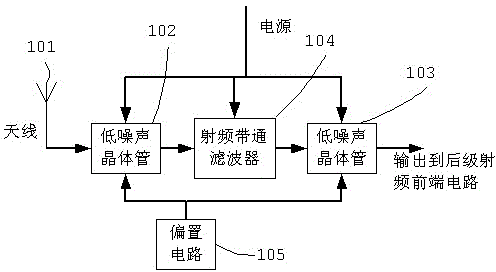
[0044] Fig. 2 is a block diagram of the new GPS active antenna of the present invention. The GPS active antenna is composed of a low noise amplifier chip 201 , a radio frequency bandpass filter 202 , and a microstrip patch antenna 203 . The GPS satellite signal is received by the microstrip patch antenna 203 , input to the low noise amplifier chip 201 and output by the radio frequency bandpass filter 202 .

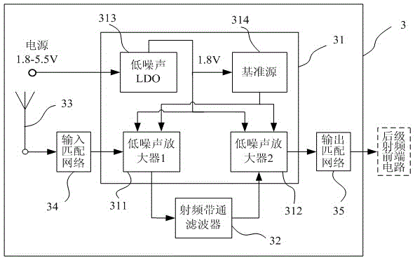
[0045] image 3 The electrical principle block diagram of the new GPS active antenna of the present invention is given. It mainly shows the internal structure of the low-noise amplifier chip: the external input voltage of 2-5 (±10%) V enters the LDO 303 inside the chip, and the LDO generates a 1.8V regulated output, which is drawn out through the chip pins for A stable power supply voltage is pr...


PUM


Abstract

The invention belongs to the technical field of radio frequency communication and provides a high-stability low-noise GPS (Global Positioning System) active antenna for solving the problems of difficulty in miniaturization and high cost of a GPS active antenna in the prior art due to the adoption of discrete components. A circuit composition of the high-stability low-noise GPS active antenna comprises two low-noise amplifiers, a radio frequency band-pass filter, a low-noise LDO (Low Drop Out Regular), a reference source and a microstrip patch antenna. According to the invention, a module comprising the low-noise amplifiers, the reference source and the low-noise LDO is integrated into a low-noise amplifier chip by adopting an integration technology, the integral GPS active antenna is formed by adopting the band-pass filter and a small amount of peripheral circuits, the area of the active antenna is reduced, the cost is saved, the power consumption is reduced and the reliability and stability are improved. The GPS active antenna provided by the invention easily meets the requirement on the miniaturization and is particularly suitable for integrating functional modules of mobile communication products such as a mobile phone, a PDA (Personal Digital Assistant), a vehicle-mounted navigator and the like, into one system.

Description

Background technique [0001] The GPS satellite navigation system can provide position, speed and time information, which can be used to locate, navigate and supervise various targets. It is omnipotent (land, ocean, aviation and aerospace), global, all-weather, continuous and real-time It plays an important role that cannot be replaced by other means in the construction of information, transportation, security and defense, agriculture, fishery, disaster prevention and relief, and environmental monitoring. Its development prospects are very broad, and it has attracted more and more attention in recent years. [0002] The technological progress of miniaturization, high precision and low power consumption of GPS chips or chipsets has effectively promoted the application and expansion of GPS satellite navigation systems in the digital consumer market, and GPS navigation based on platforms such as PDAs, mobile phones, and digital players has emerged Locate the device. However, these...

Claims


Application Information

Patent Timeline
IPC IPC(8): H01Q23/00H01Q1/38H01Q1/48H01Q13/08
CPCY02B60/50
Inventor 段炼甘业兵钱敏马成炎
Owner HANGZHOU RUIMENG TECH
Learn More