Horizontal oil-fired and gas-fired efficient energy-saving boiler

A high-efficiency, energy-saving and fuel-efficient technology, applied in the field of boilers, can solve the problems of increased manufacturing difficulty and production cost, increased boiler exterior design parameters, cracking of the front tube sheet of the re-combustion chamber, etc., and achieves good combustion conditions and saves equipment. Investment cost, effect of eliminating ventilation resistance

Active Publication Date: 2012-08-01
仲伟军
View PDF8 Cites 11 Cited by
  • Summary
  • Abstract
  • Description
  • Claims
  • Application Information

AI Technical Summary

Problems solved by technology

However, this kind of backfire chamber structure requires complicated manufacturing process, time-consuming and material-consuming. When the product is put into operation, due to the extremely high temperature of the backfire chamber, it is very easy to cause the front tube plate of the backfire chamber to crack and cannot be repaired.
Cause safety hazards, leading to product scrap
For oil and gas boilers with large tonnage, conical heads are arranged at the front and rear ends of the corrugated furnace, and the corrugated furnace structure is used in the middle, while the back part is still arranged with a larger size and larger water space in the furnace. room, resulting in the increase of the design parameters of the boiler, making the manufacturing difficulty and production cost increase

Method used


Image

  • Horizontal oil-fired and gas-fired efficient energy-saving boiler
  • Horizontal oil-fired and gas-fired efficient energy-saving boiler
  • Horizontal oil-fired and gas-fired efficient energy-saving boiler

Examples


Embodiment Construction

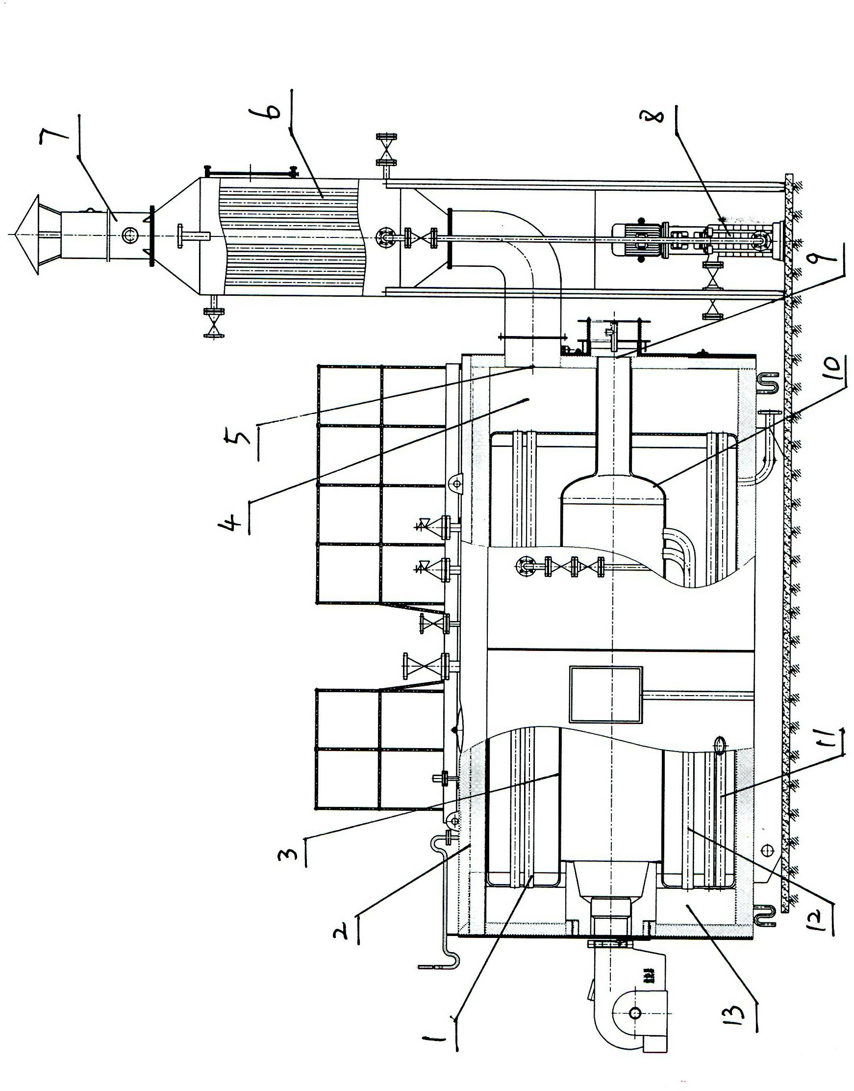
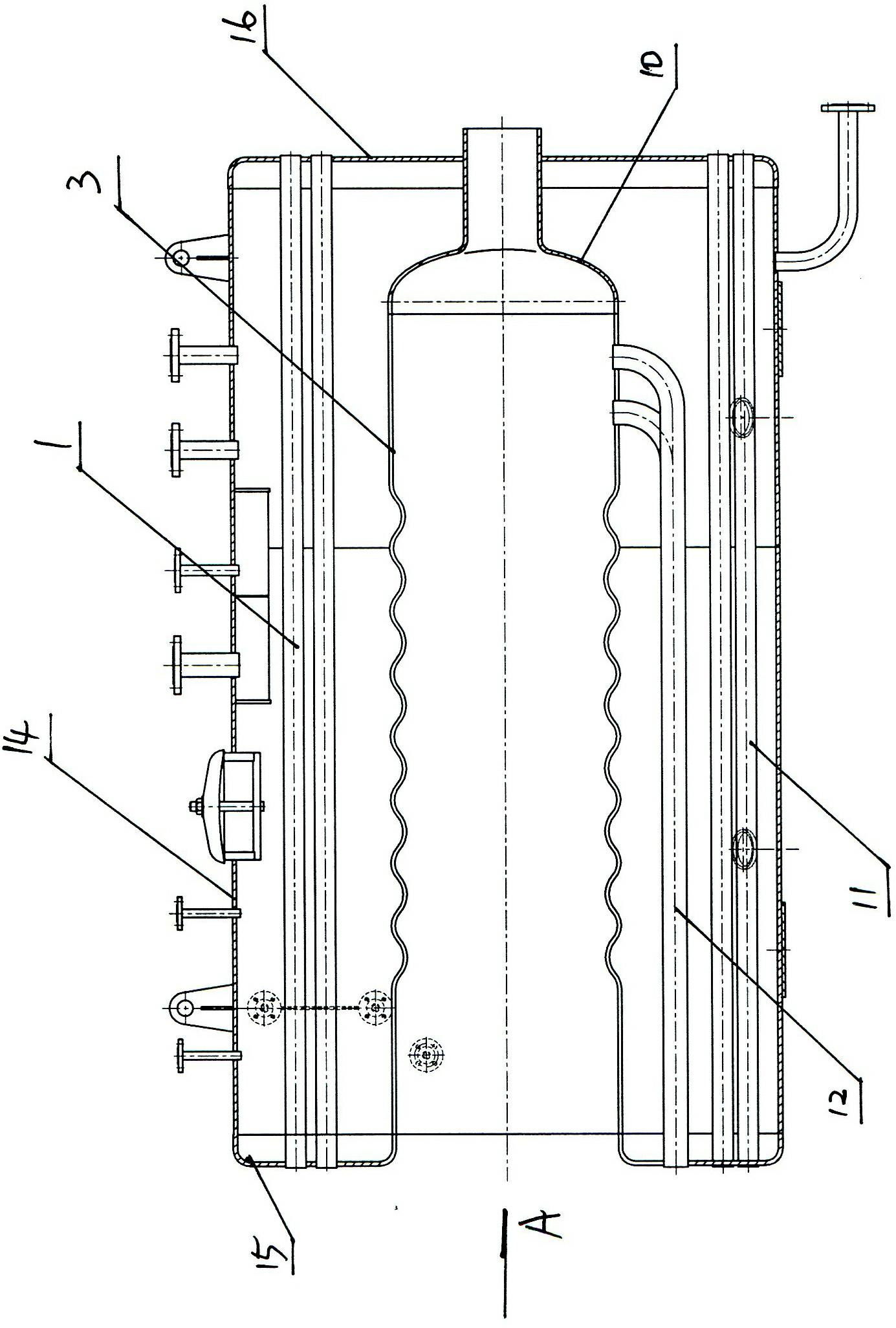
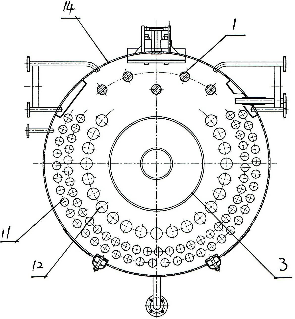
[0012] A horizontal oil-fired gas-fired high-efficiency energy-saving boiler, including a drum 14, the outer surface of the drum 14 is covered with an insulating layer 2, and the inside of the drum 14 is provided with a furnace 3 connected to the burner, and at the inner end of the furnace 3 A rear head 10 is provided, an explosion-proof device 9 is arranged at the rear head 10, a second return pipe 12 of an inner ring and a third return pipe 11 of an outer ring are arranged on the periphery of the furnace 3, and the front pipe of the drum 14 The front portion of the plate 15 is provided with a front smoke box 13, and the rear portion of the rear tube plate 16 of the drum 14 is provided with a rear smoke box 4, and the rear smoke box 4 is provided with a smoke outlet 5, and the front end of the second return pipe 12 is connected to the The front smoke box 13 is connected, and the rear end of the second return pipe 12 is arranged as an elbow, and the elbow at the rear end of the...


PUM


Abstract

The invention discloses a horizontal oil-fired and gas-fired efficient energy-saving boiler, which comprises a boiler barrel; a boiler furnace connected with a burner is arranged in the boiler barrel; a rear end enclosure is arranged at the inner end of the boiler furnace; an explosion-proof device is arranged at the rear end enclosure; an inner ring second return pipe and an outer ring third return pipe are arranged on the periphery of the boiler furnace; a front smoke box is arranged on the front part of a front tube plate of the boiler barrel; a rear smoke box is arranged on the rear part of a rear tube plate of the boiler barrel; the rear smoke box is provided with a smoke outlet; an elbow is arranged at the rear end of the second return pipe; the elbow at the rear end of the second return pipe is connected with the wall of the boiler furnace close to the rear end enclosure; the total smoke outlet area of the second return pipe is larger than the area of the smoke outlet of the rear smoke box; a plurality of direct-pull reinforcing round pipes connected with the front tube plate and the rear tube plate of the boiler barrel are arranged on the upper part of the boiler barrel; and an energy-saving heat exchanger for recovering tail gas is arranged at the smoke outlet. Under the condition of the same water capacity, the boiler barrel is smaller in size, the structure of the boiler is more compact, the manufacturing cost is reduced, and the heated area can be increased by 3 to 5 percent.

Description

technical field [0001] The invention relates to a boiler, in particular to a horizontal fuel gas high-efficiency energy-saving boiler. Background technique [0002] The structure of the traditional oil and gas boilers adopts the structure of the combustion chamber to achieve the purpose of arranging the return channel and the return heating surface. However, the manufacturing process of this backfire chamber structure is complicated, time-consuming and material-consuming. When the product is put into operation, due to the extremely high temperature of the backfire chamber, it is very easy to cause the front tube plate of the backfire chamber to crack and cannot be repaired. Cause safety hazards, directly lead to product scrapping. For oil and gas boilers with large tonnage, conical heads are arranged at the front and rear ends of the corrugated furnace, and the corrugated furnace structure is used in the middle, while the back part is still arranged with a larger size and ...

Claims


Application Information

Patent Timeline
IPC IPC(8): F22B31/08F22D1/02F24H1/34F24H9/00
Inventor 仲伟军
Owner 仲伟军
Why Eureka
Try Eureka