Glue injection and injection molding method for inductors

A technology for inductive components and glue injection, applied in the direction of coating, etc., can solve problems such as constraints, low inductance, and increased manufacturing costs

Active Publication Date: 2012-08-01
广州易力日拓电子科技有限公司
View PDF3 Cites 5 Cited by
  • Summary
  • Abstract
  • Description
  • Claims
  • Application Information

AI Technical Summary

Problems solved by technology

In general high-pressure injection molding methods, due to the poor fluidity of plastic raw materials, extreme pressure (200bar to 1300bar) is required to force the injection. The molten plastic with extremely high pressure can easily pierce the tape, and the extruded coil will shift and the magnetic core will deform, resulting in inductance. Disadvantages such as low

Method used


Image

  • Glue injection and injection molding method for inductors
  • Glue injection and injection molding method for inductors
  • Glue injection and injection molding method for inductors

Examples


Embodiment 1

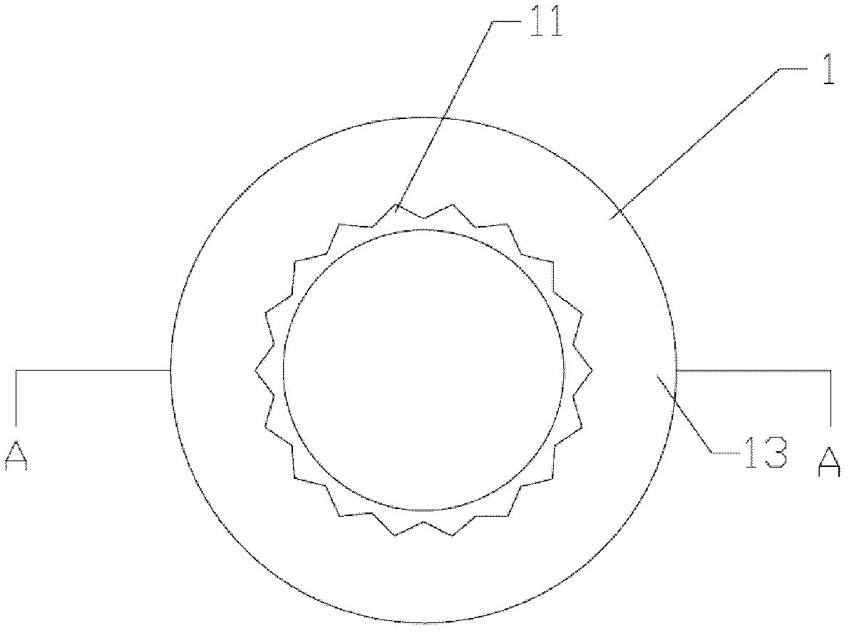
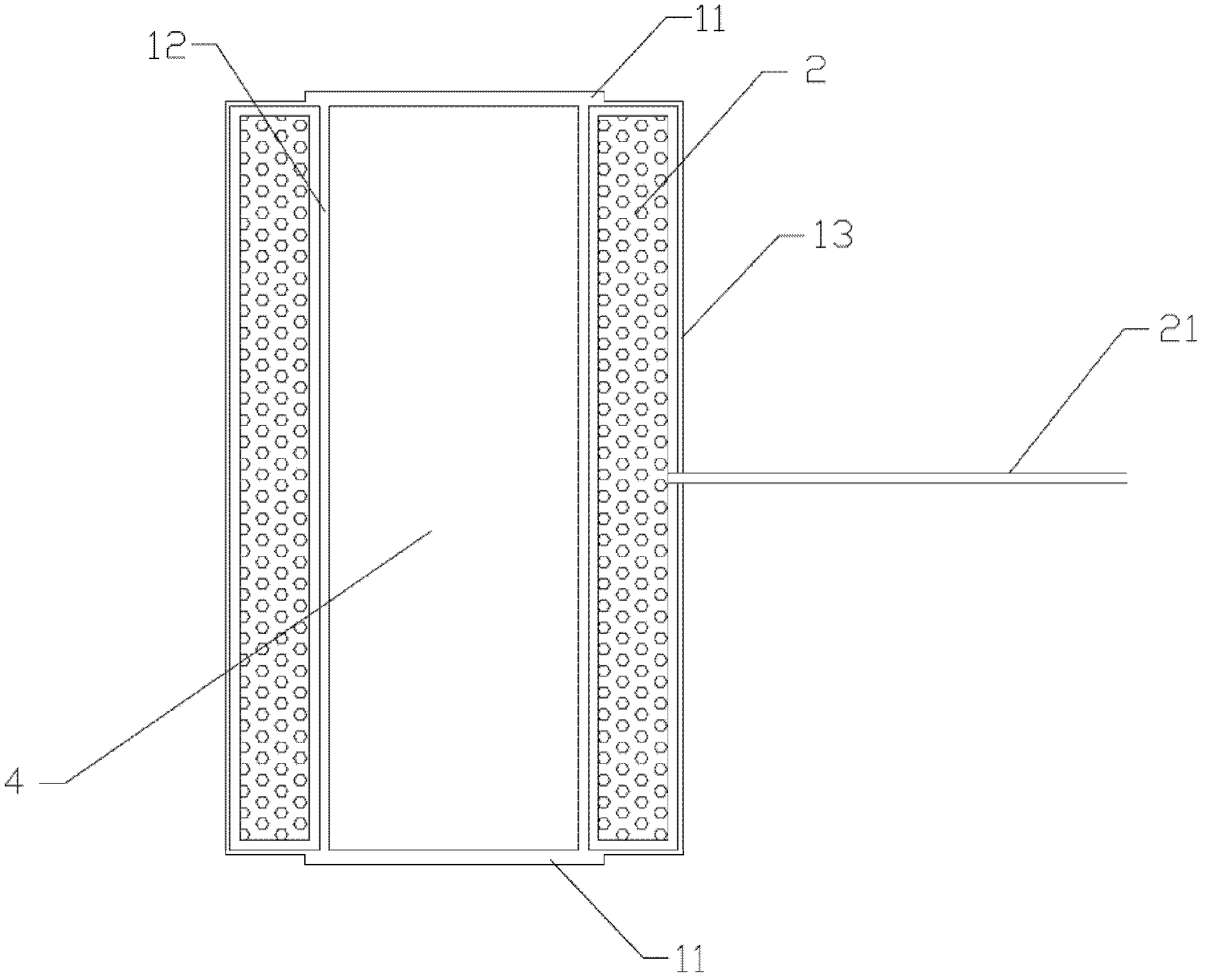
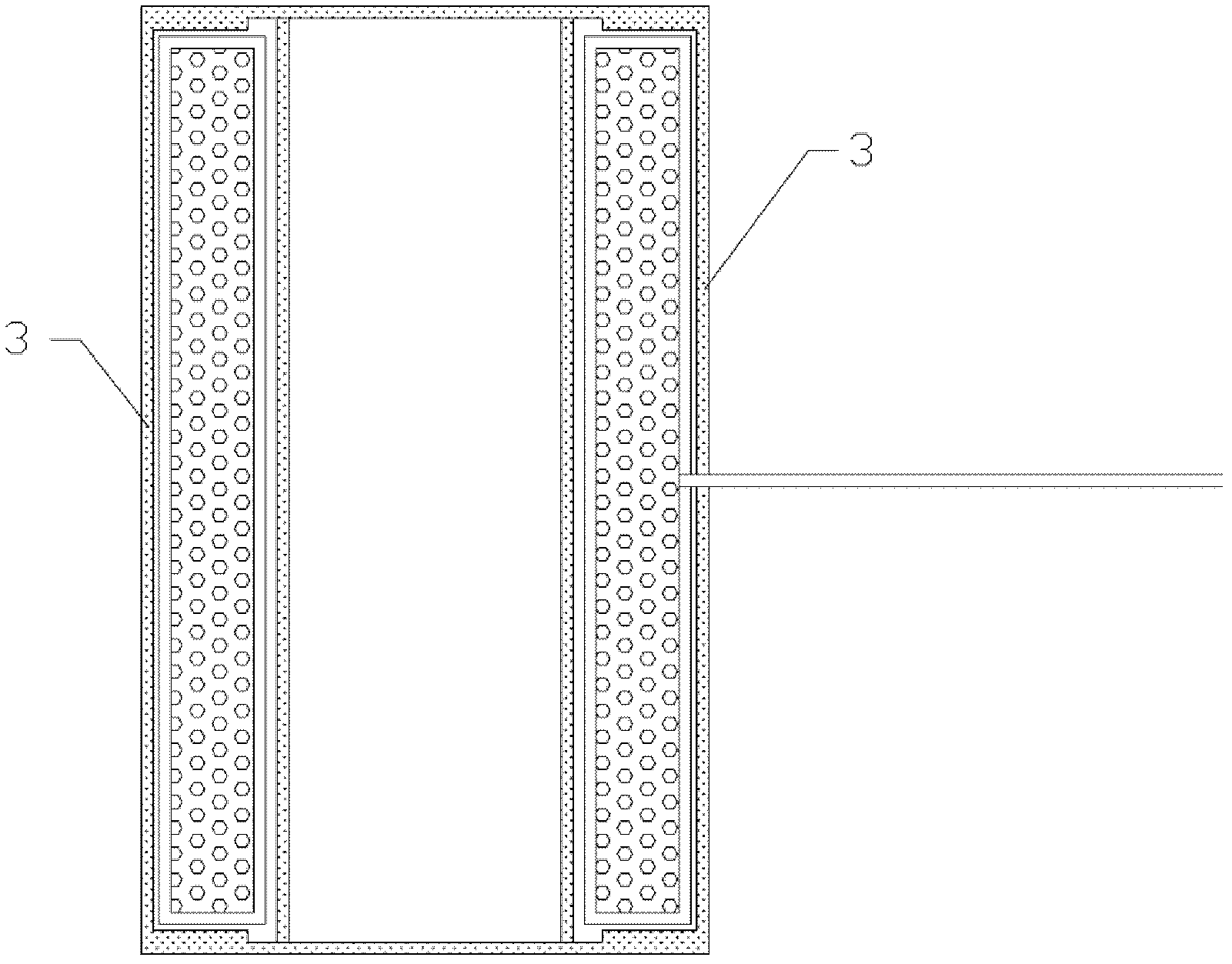
[0025] Such as figure 1 , figure 2 with image 3 As shown, the injection and injection molding method of the inductance element in this embodiment includes the inner layer injection of the first stage and the outer layer injection molding of the second stage:

[0026] The inner layer glue injection is to install a steel mold in a vertical low-pressure glue injection machine, place the inductance element 2 with an iron cover in the steel mold, and put the inductance coil lead-out line 21 of the inductance element 2 into the mold channel And lead out of the steel mold, operate the vertical low-pressure glue injection machine to cover the mold, inject the hot melt adhesive OM646 under the pressure of 5-40bar, and fill the steel mold, and inject a layer of glue on the outer circumference of the inductance element and the through hole 4 , thereby forming the adhesive layer 1, the adhesive layer 1 includes the peripheral adhesive 13 and the annular adhesive 12 adapted to the shap...


PUM


Abstract

The invention discloses a glue injection and injection molding method for inductors, which includes inner glue injection and outer injection molding. In inner glue injection, at least a through hole of one inductor is filled with a circular glue layer the same as the through hole in shape, two ends of the circular glue extend out of two end faces of the inductor, the outer peripheral face of the extension end is serrated, and accordingly a semi-finished inductor is obtained. In outer injection molding, subjecting the outer periphery and the through hole of the semi-finished inductor element are subjected to injection molding. A plastic layer at least covers an extension end of the circular glue, so that the plastic layer is meshed with the serrated outer periphery of the extension end. The inductors produced by the method are high in temperature and humidity resistance, fine in insulativity, stable in inductance and low in cost.

Description

Technical field: [0001] The invention relates to a method for manufacturing an inductance element, such as a method for manufacturing a current sensor and a voltage sensor, in particular to a method for injecting glue and molding an inductance element. Background technique: [0002] In the field of motor power applications, inductive components are widely used. Inductance components need to pass the test of high voltage insulation and high temperature and high humidity environment such as instantaneous lightning strike. In general high-pressure injection molding methods, due to the poor fluidity of plastic raw materials, extreme pressure (200bar to 1300bar) is required to force the injection. The molten plastic with extremely high pressure can easily pierce the tape, and the extruded coil will shift and the magnetic core will deform, resulting in inductance. Disadvantages such as low and poor precision, low yield rate, increased manufacturing costs, especially after long-te...

Claims


Application Information

Patent Timeline
IPC IPC(8): B29C45/14
Inventor 呂金宝
Owner 广州易力日拓电子科技有限公司
Why Eureka
Try Eureka