
Ejection mechanism of fixed die push plate

A technology of ejecting mechanism and fixed template, applied in the field of mold accessories, can solve the problems of uneven distribution of ejection force, failure to reach the deformation of ejected products, clamping mold, etc., and achieve the effect of solving unqualified mold products and ingenious structure.

Active Publication Date: 2012-08-01
宁波市优美屹科技有限公司
View PDF3 Cites 5 Cited by
  • Summary
  • Abstract
  • Description
  • Claims
  • Application Information

AI Technical Summary

Problems solved by technology

[0002] In the current mold production process, during the die-casting operation, the product is easy to stick to the mold and deform, and the national quality inspection standard has certain requirements for the degree of deformation of the product. Generally, the degree of deformation should be lower than the deformation requirements of plastic processing. To avoid product damage caused by plastic processing in the later stage, which reduces the qualified rate of finished products
In order to solve the above problems, the ejection mechanism is generally installed on the mold, but the structure of the existing ejection mechanism is relatively complicated, and the distribution of the ejection force is uneven, which is easy to cause the mold to be jammed, so that the product cannot be ejected and the deformation is reduced. the goal of

Method used


Image

  • Ejection mechanism of fixed die push plate
  • Ejection mechanism of fixed die push plate
  • Ejection mechanism of fixed die push plate

Examples


Embodiment 1

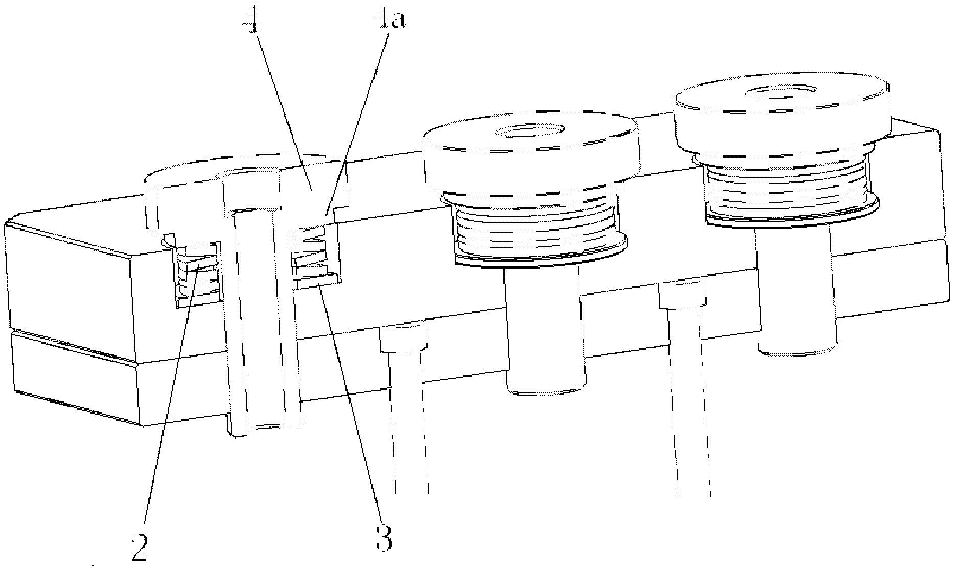
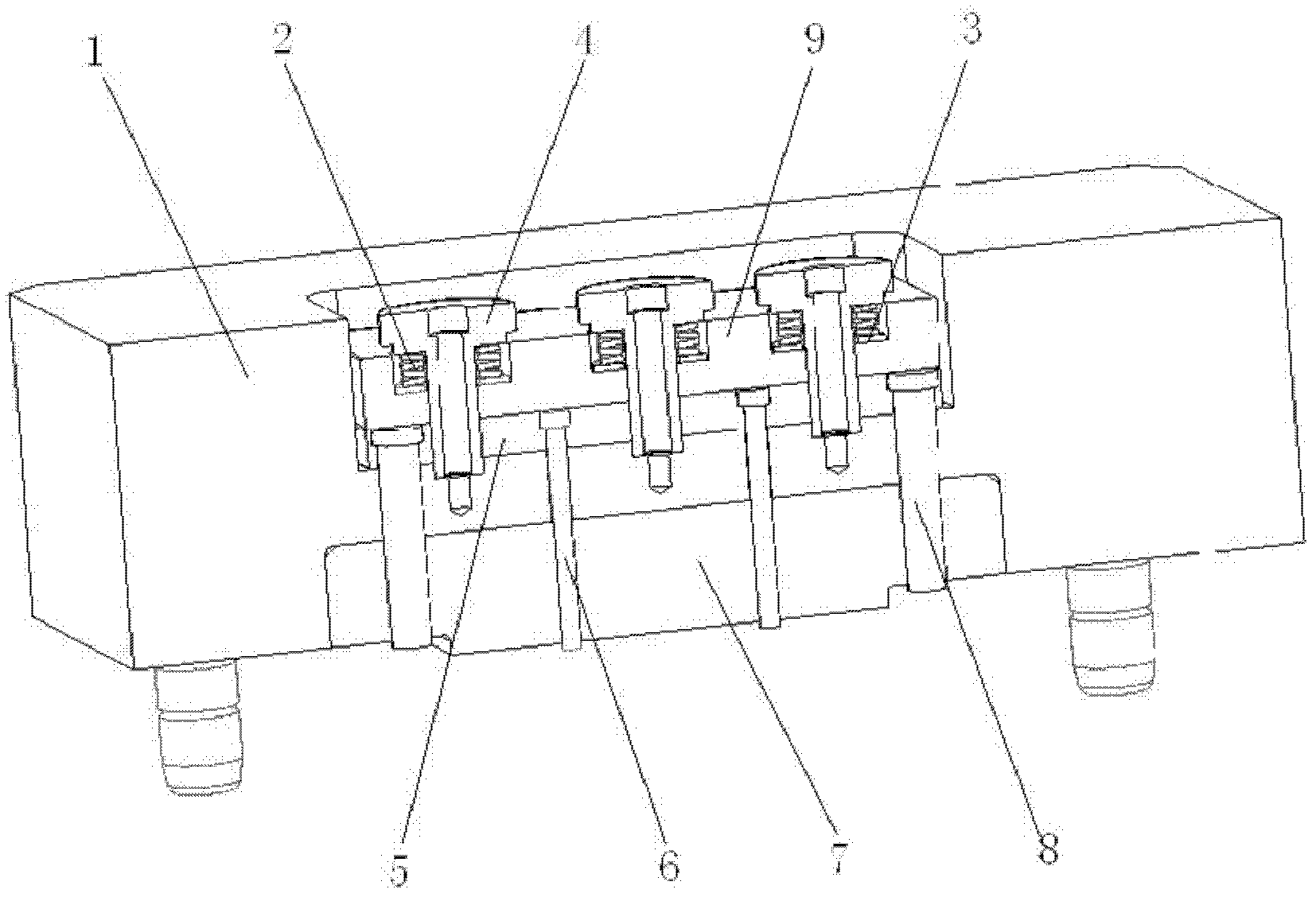
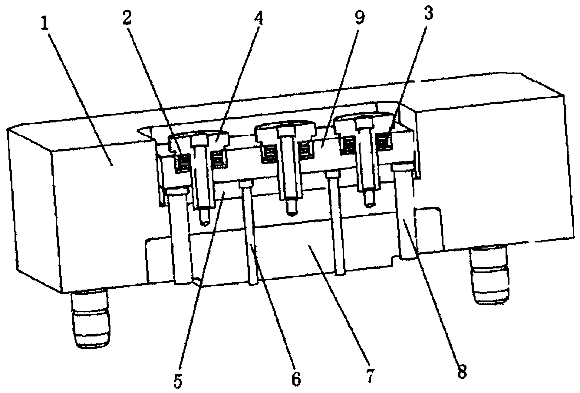
[0015] Such as figure 1 , figure 2 A fixed mold push plate ejection mechanism is shown, including a fixed template 1, a butterfly spring 2, a gasket 3, a guide rod 4, a push rod fixing plate 5, a push rod 6, a fixed inner mold 7, a reset rod 8, a push rod Plate 9, two corresponding mounting grooves are arranged on the upper and lower sides of the fixed template 1, and a push rod fixing plate 5 and a push pedal 9 are installed in the mounting groove above the fixed template 1 from bottom to top; There is a mounting hole, and the mounting hole is T-shaped; on the T-shaped shoulder of the mounting hole, there is a spacer 3 and several disc springs 2 from bottom to top, and a guide rod is set on the spacer 3 and disc spring 2 4. The guide rod 4 is T-shaped and has a threaded hole in the middle. The top surface of the guide rod head 4a is flush with the top surface of the fixed inner mold 7. A small round platform protrudes from the bottom surface of the guide rod head 4a, and th...


PUM


Abstract

The invention relates to an ejection mechanism of a fixed die push plate, which comprises a fixed die plate. Two corresponding installation grooves are arranged on the upper face and the lower face of the fixed die plate, an ejector pin retaining plate and a push plate are installed in the installation groove on the upper face of the fixed die plate from bottom to top, and three T-shaped installation holes are installed on the upper face of the push plate at equal intervals. A gasket and a plurality of belleville springs are padded on T-shaped shoulders of the installation holes from bottom to top, T-shaped guide bars are sleeved on the gasket and the belleville springs, and the lower portions of the heads of the guide bars protrude out to form small circular truncated cones which are in clearance fit with the T-shaped shoulders of the installation holes. The lower face of the push plate between every two installation holes abuts against an ejector pin. A fixed inner die is arranged in the installation groove on the lower face of the fixed die plate, release rods are installed on the left side and the right side of the fixed inner die, and the heads of the release rods abut against two sides of the lower face of the push plate. The ejection mechanism adopts the belleville springs to serve as pushing power producers, achieves fixed die auxiliary pushing functions during die sinking, and is ingenious in structure, even in pushing force distribution, and capable of improving force distribution quality of products.

Description

technical field [0001] The invention belongs to the field of mold accessories, and in particular relates to an ejection mechanism of a push plate of a fixed mold. Background technique [0002] In the current mold production process, during the die-casting operation, the product is easy to stick to the mold and deform, and the national quality inspection standard has certain requirements for the degree of deformation of the product. Generally, the degree of deformation should be lower than the deformation requirements of plastic processing. In order to avoid product damage caused by plastic processing in the later stage, the qualified rate of finished products will be reduced. In order to solve the above problems, the ejection mechanism is generally installed on the mold, but the structure of the existing ejection mechanism is relatively complicated, and the distribution of the ejection force is uneven, which is easy to cause the mold to be jammed, so that the product cannot ...

Claims


Application Information

Patent Timeline
Patent Type & Authority Applications(China)
IPC IPC(8): B22D17/22
Inventor 陈九戬
Owner 宁波市优美屹科技有限公司
Learn More