Transient electromagnetic field excitation system for transcranial magnetic stimulation (TMS) in medical field
A technology of excitation system and electromagnetic field, which is applied in the field of medical instruments, can solve problems such as the difficulty in realizing the hardware circuit of the excitation system, the large drive current of the excitation system, and the large pulse width, so as to reduce the current amplitude, overcome the difficulties in implementation, and reduce the nerve stimulation effect. Effect
- Summary
- Abstract
- Description
- Claims
- Application Information
AI Technical Summary
Problems solved by technology
Method used
Image
Examples
Embodiment 1
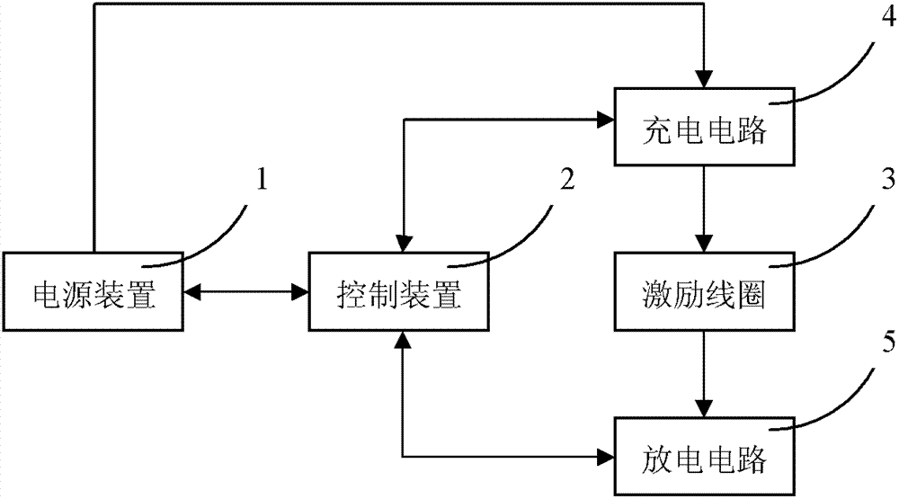
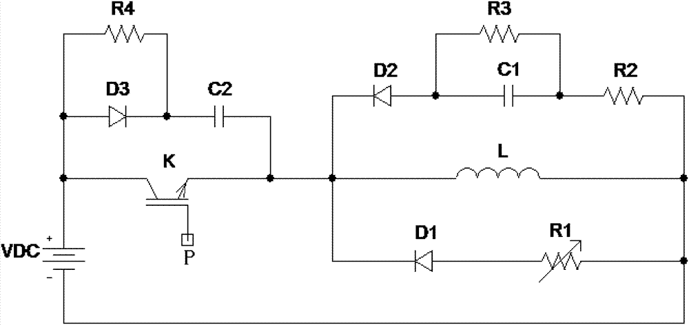
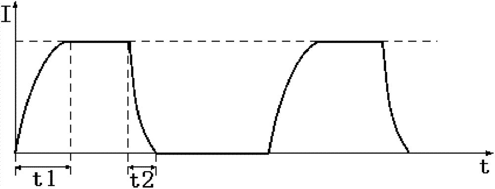
[0034] The structure of the transient electromagnetic field excitation system in this example is as figure 2 As shown, the power supply device in this example is a DC power supply VDC, and its output voltage can be passed through the control device ( figure 1 (Not shown in)) to adjust the charging voltage to change the excitation current amplitude of the excitation coil L. figure 2 The semiconductor switching device K constitutes the charging switch of this example, and the control pole P of the semiconductor switching device K is connected to the control device, which can control the charging and discharging time (frequency) of the excitation coil L and adjust the excitation current amplitude of the excitation coil L. figure 2 The middle resistor R4, the diode D3 and the capacitor C2 constitute the absorption circuit of the semiconductor switching device K. The discharge resistor R1 and the discharge diode D1 are connected in series and connected in parallel at both ends of th...
Embodiment 2
[0039] In this example, the transient electromagnetic field excitation system uses the discharge of the capacitor to excite the excitation coil. Its circuit structure is as follows Figure 4 Shown. The charging circuit of this example includes a current-limiting resistor R0, a charging capacitor C, and a charging switch K1, and the discharging circuit includes a discharging switch K2, an excitation coil L, and a discharging resistor R. The power supply device VDC is connected to the charging capacitor C through the charging switch K1, and the voltage of the charging capacitor C can be controlled by controlling the output voltage of the power supply device VDC and / or the on-time of the charging switch K1. Figure 4 Among them, the charging capacitor C is connected to the excitation coil L through the discharge switch K2, and the discharge switch K2 and the discharge resistor R are connected in series with the excitation coil L. In this example, the charging switch K1 and the disc...
PUM
 Abstract
Description
Claims
Application Information
 - R&D Engineer
- R&D Manager
- IP Professional
- Industry Leading Data Capabilities
- Powerful AI technology
- Patent DNA Extraction
Browse by: Latest US Patents, China's latest patents, Technical Efficacy Thesaurus, Application Domain, Technology Topic, Popular Technical Reports.
© 2024 PatSnap. All rights reserved.Legal|Privacy policy|Modern Slavery Act Transparency Statement|Sitemap|About US| Contact US: help@patsnap.com


