
Silicon wafer directly-bonded micro-mechanical gyroscope based on silicon through hole technology

A micromachined gyroscope, direct bonding technology, used in steering sensing devices and other directions

Active Publication Date: 2012-07-25
NORTH ELECTRON RES INST ANHUI CO LTD
View PDF3 Cites 6 Cited by
  • Summary
  • Abstract
  • Description
  • Claims
  • Application Information

AI Technical Summary

Problems solved by technology

However, these bonding eutectic materials and isolation materials will more or less bring about some mismatched thermal stress problems, which will affect device performance

Method used


Image

  • Silicon wafer directly-bonded micro-mechanical gyroscope based on silicon through hole technology
  • Silicon wafer directly-bonded micro-mechanical gyroscope based on silicon through hole technology
  • Silicon wafer directly-bonded micro-mechanical gyroscope based on silicon through hole technology

Examples


Embodiment Construction

[0033] The present invention will be further described below in conjunction with the embodiments shown in the accompanying drawings.

[0034] See attached figure 1 to attach Figure 6 shown.

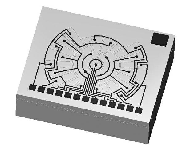
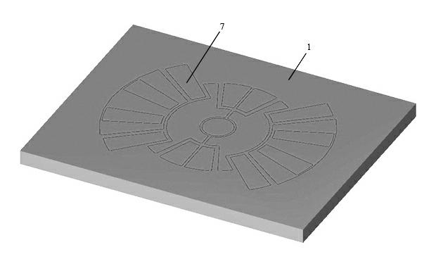
[0035] A micromechanical gyroscope based on the direct bonding of silicon wafers based on through-silicon via technology, which includes three layers of silicon wafer layers directly bonded to silicon-silicon, and the three layers of silicon wafer layers are sequentially fixed electrode wafer layers 1 , the mass block wafer layer 2 , and the capping wafer layer 3 . The materials of the three silicon wafer layers are all highly doped single crystal silicon.

[0036] The fixed electrode wafer layer 1 is a through-hole silicon wafer layer, which has a plurality of through-hole silicon electrodes 7 perpendicular to the through-hole silicon wafer layer, and there are through-hole silicon electrodes 7 perpendicular to the through-hole silicon wafer layer between adjacent through-hole silic...


PUM


Abstract

The invention relates to a silicon wafer directly-bonded micro-mechanical gyroscope based on a silicon through hole technology, comprising three silicon wafer layers in a silicon-silicon direct bonding mode, namely, a fixing electrode silicon wafer layer, a mass block silicon wafer layer and a sealing cover silicon wafer layer; the fixing electrode silicon wafer layer is a through hole silicon wafer layer and is provided with a plurality of through hole silicon electrodes vertical to the through hole silicon wafer layer, and through hole silicon insulating layers vertical to the through hole silicon wafer layers are arranged between the adjacent through hole silicon wafer layers; the mass block silicon wafer layer comprises a pair of eudipleural fan-shaped mass blocks, the fan-shaped mass blocks form mass block electrodes, and the mass block silicon wafer layer is symmetrically suspended below the fixing electrode silicon wafer layer through a single anchor point in the silicon-silicon direct bonding mode; and the mass block electrodes and the through hole silicon electrodes form two electrodes of a variable capacitor. According to the invention, through hole silicon is used as an electrode material of a variable capacitor sensor structure and the silicon-silicon direct bonding mode is utilized for reducing the thermal stress to be minimum and the sensor performance is improved.

Description

technical field [0001] The invention relates to a capacitive micro-mechanical gyroscope, in particular to a micro-mechanical gyroscope based on silicon wafer direct bonding based on through-silicon hole technology. Background technique [0002] Silicon micromachined gyroscopes have broad application prospects in the field of inertial measurement due to their small size, low cost, low power consumption, shock resistance, and high reliability. The capacitive silicon micromachined gyroscope has attracted widespread attention due to its low temperature coefficient and good repeatability. It is one of the most developed and widely used inertial devices. [0003] At present, there are many design structures of capacitive silicon mechanical gyroscopes, but they can be roughly divided into two categories: one is an annular (or fan-shaped) mass block with an arc-shaped comb structure, and this type of gyroscope structure generally adopts a single fulcrum structure, that is to say, t...

Claims


Application Information

Patent Timeline
Patent Type & Authority Applications(China)
IPC IPC(8): G01C19/56
Inventor 郭述文
Owner NORTH ELECTRON RES INST ANHUI CO LTD
Learn More