Eureka AIR delivers breakthrough ideas for toughest innovation challenges, trusted by R&D personnel around the world.

LED light emitting device

A technology for light-emitting devices and LED light sources, which is applied in lighting devices, fixed lighting devices, components of lighting devices, etc. Soft, easy-to-install effect

Inactive Publication Date: 2012-07-25
XI AN FORLED NEW ENERGY TECH & ENGCO
View PDF5 Cites 3 Cited by
  • Summary
  • Abstract
  • Description
  • Claims
  • Application Information

AI Technical Summary

Problems solved by technology

The problem brought about by this integral structure LED lighting fixture is: the failure of any link in these multiple LED chip light sources connected in series and the constant current drive device can cause the failure of the entire lamp, and even professionals It is also difficult to simply and directly determine whether a certain LED chip is faulty or the drive device is faulty, so it can only be replaced as a whole. Equivalent to the cost of installing new lamps, which hinders the popularization and use of LED energy-saving lighting lamps
[0005] Due to the above problems, there are few existing ceiling lamps and chandeliers that use LEDs as light sources.

Method used


Image

  • LED light emitting device
  • LED light emitting device
  • LED light emitting device

Examples


Embodiment 1

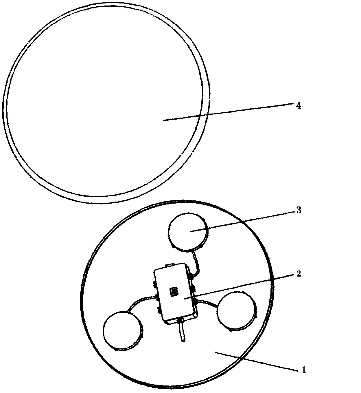
[0029] see figure 1 , an LED lighting device, including a lamp holder 1 and a lampshade 4, the lamp holder is a lamp holder with a metal mounting substrate, three LED light sources 3 and a driving power supply 2 are arranged on the lamp holder, and the three LED light sources 3 are all connected to the The driving power supply 2 is connected and driven to emit light. The LED light source 3 can be flexibly arranged according to requirements, so as to overcome the point light source characteristics of LED lamps, so that the illumination light is soft and uniform, and meets the requirements of indoor lighting effect.

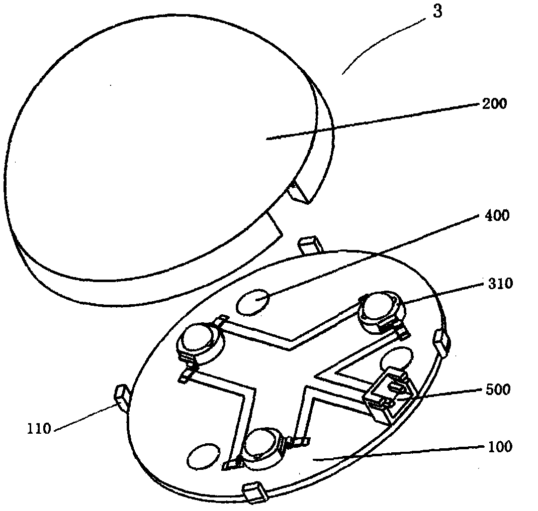
[0030] see figure 2 , in this embodiment, the LED light source 3 includes an aluminum substrate 100 and a translucent cover 200 corresponding to the aluminum substrate, the aluminum substrate 100 is provided with buckles 110, and the translucent cover 200 is provided with buckles ( Not shown in the figure), when in use, the light-transmitting cover and the alumi...

Embodiment 2

[0038] Figure 4 The LED light-emitting device shown includes a lamp holder and a lampshade. Six LED light sources and two driving power sources are arranged on the lamp holder. The structures of the LED light sources and the driving power sources are basically the same as those in Embodiment 1, and the six LED light sources are arranged in two rows. Arranged in three rows, the two driving power sources are connected together through the mains input socket and the spare mains output socket to jointly provide power drive for the LED light source.


PUM


Abstract

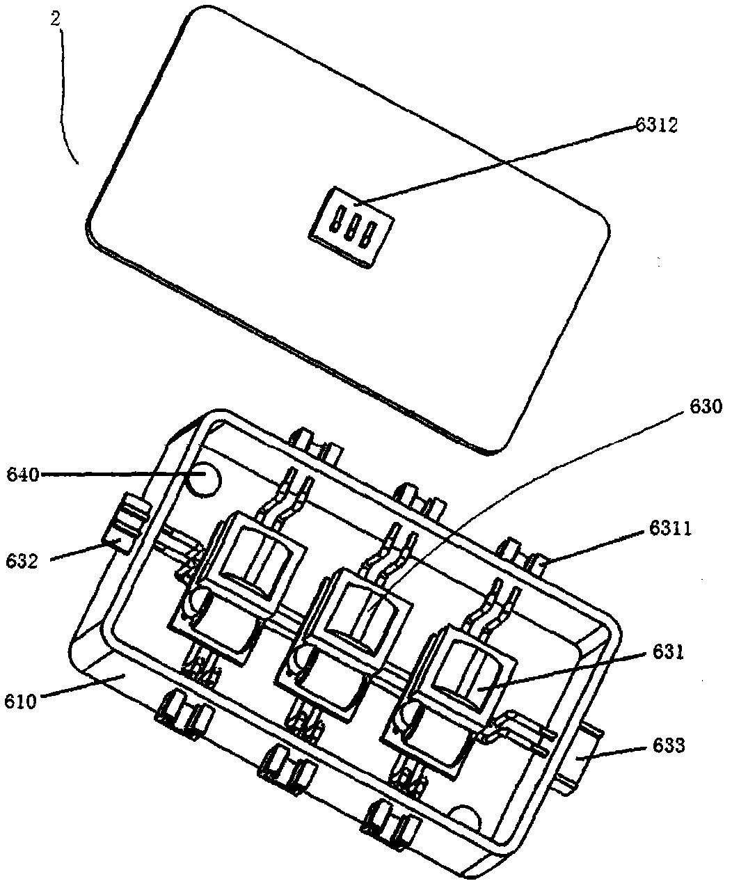
The invention relates to an LED light emitting device which comprises a lamp holder and a lamp shade. The lamp holder is provided with a plurality of LED light sources and a driving power supply. The LED light source comprises an aluminum substrate and a light transmitting cover. The aluminum substrate is provided with a plurality of LED light emitting chips connected with one another in series and a socket interface. The driving power supply comprises a power supply module group consisting of a plurality of LED driving power supply modules in a housing. The power supply module group comprises an electric supply input socket and a spare electric supply output socket. The LED driving power supply modules are connected in parallel. The LED driving power supply module comprises a low voltage output socket. The LED light sources are respectively connected with the low voltage output socket of the driving power supply. The LED light sources provided by the invention can be arranged agilely according to demand. When certain LED driving power supply module or an LED light source malfunctions, work of other power supplies and light sources are not influenced. The LED light emitting device is simple and convenient to install, overhaul and maintain.

Description

technical field [0001] The invention relates to an LED lighting device, which can be used as a ceiling lamp or a pendant lamp. Background technique [0002] LED is a light-emitting diode, which is a solid semiconductor device that can directly convert electrical energy into visible light. It has the advantages of small size, low energy consumption, high light efficiency, long service life, and low heat generation. Following incandescent lamps and tri-primary fluorescent lamps, LEDs as lighting sources are called the third generation of energy-saving lighting sources. Their development trend is bound to enter thousands of households and replace the widely used incandescent lamps and tri-primary fluorescent energy-saving lamps. If LEDs replace half of incandescent and fluorescent lamps, energy equivalent to more than 10 billion liters of crude oil can be saved every year, and the generation of carbon dioxide and other greenhouse gases can be reduced, and the living environmen...

Claims


Application Information

Patent Timeline
IPC IPC(8): F21S8/04F21S8/06F21V17/12F21V19/00F21V23/06F21V23/04F21Y101/02F21Y115/10
Inventor 刘铭昝小波杨要涛吴继明刘建永汪维君高陇平
Owner XI AN FORLED NEW ENERGY TECH & ENGCO
Why Eureka
Eureka Blog
Learn More