
Cylinder head guide column drilling rectifying tool and application method

A cylinder head and column hole technology, which is applied in the field of cylinder head drilling guide column hole correction tools, can solve the problems of high size and position accuracy requirements

Active Publication Date: 2012-07-25
JIANGSU HIDA MARINE VALVE
View PDF9 Cites 5 Cited by
  • Summary
  • Abstract
  • Description
  • Claims
  • Application Information

AI Technical Summary

Problems solved by technology

The position of the mounting hole of the guide post is at the midpoint of the mounting holes of the upper and lower conduits, which requires high precision in size and position, and the holes processed by the drilling jig cannot meet the requirements of the product drawing

Method used


Image

  • Cylinder head guide column drilling rectifying tool and application method
  • Cylinder head guide column drilling rectifying tool and application method

Examples


Embodiment Construction

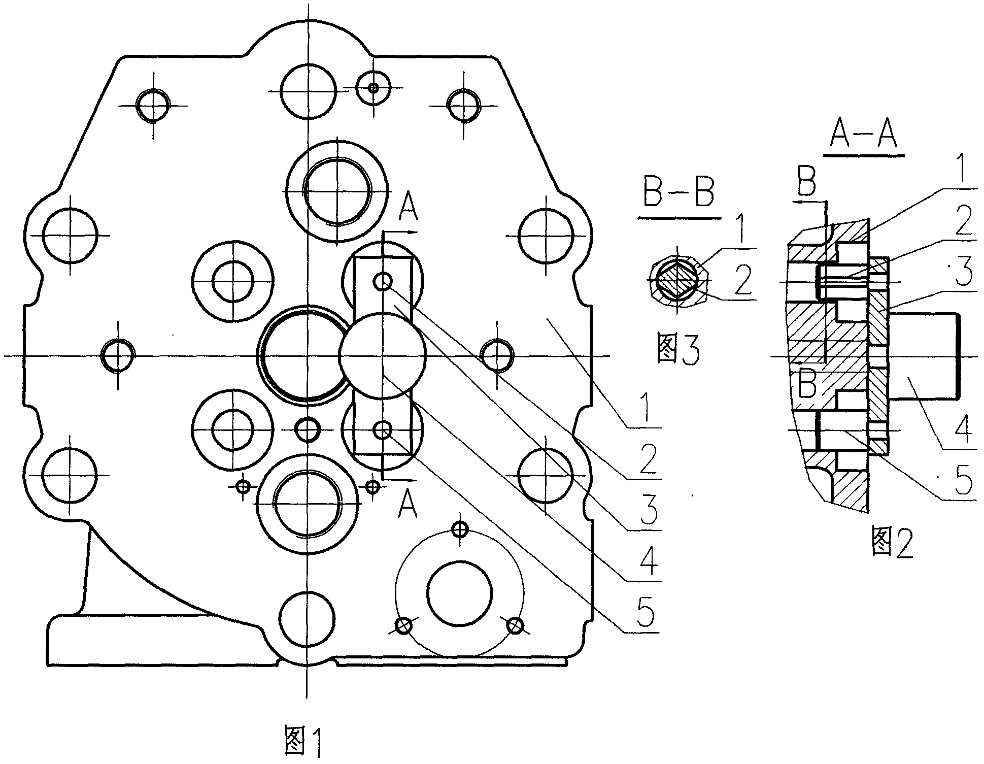
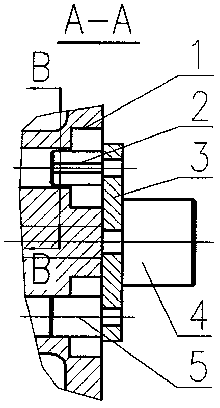
[0012] The accompanying drawing is an assembly drawing of the drill guide post hole correction tool for the cylinder head (1) of a 16V240ZJ diesel engine.

[0013] Referring to the accompanying drawings, the diameter of the conduit installation hole of the 16V240ZJ diesel engine cylinder head (1) is 28mm. The diameter of the guidepost hole is 22mm. The distance between the two conduit holes on the same side is 104±0.2mm. middle. The conduit mounting hole must be processed from the combustion face of the cylinder head (1) together with its coaxial valve seat hole, and the guide post hole will be processed from the other side of the cylinder head (1). According to the working principle of the cylinder head (1), the guide post holes on the same side are associated with the conduit mounting holes. The position of the guide post hole is determined by the position of the cylinder head (1) conduit mounting hole, and the positioning reference of the calibration tool is exactly the tw...


PUM


Abstract

Disclosed are an application method of a cylinder head guide column drilling rectifying tool. A diamond pin is mounted on the upper edge of a plate, an aligning column is mounted in the middle of the plate, a circular positioning pin is mounted on the lower edge of the plate, axes of the diamond pin, the aligning column and the circular positioning pin are positioned in the same plane and are parallel to each other, the diamond pin and the circular positioning pin are respectively mounted in valve guide pipe mounting holes of a cylinder head, and the distance from the axis of the diamond pin to the axis of the aligning column is equal to that from the axis of the circular positioning pin to the axis of the aligning column. The application method of the tool includes mounting the circular positioning pin in the lower valve guide pipe mounting hole, mounting the diamond pin in the upper valve guide pipe mounting hole, leading the aligning column to be coaxial with a spindle, and locating the spindle at a position a; mounting the circular positioning pin in the upper valve guide pipe mounting hole, mounting the diamond pin in the lower valve guide pipe mounting hole, leading the axis of the aligning column to be coaxial with the axis of the spindle of a boring mill, and locating the spindle at a position b; and shifting the spindle of the boring mill to a position between the position a and the position b, and drilling a guide column hole. The tool is reasonable in positioning and high in drilling precision.

Description

Technical field [0001] The invention relates to mechanical processing technology equipment, in particular to a cylinder head drilling guide post hole correction tool and a using method. Background technique [0002] Most of the current high-power internal combustion engines use a cylinder head for one cylinder, and many holes are arranged on the upper plate surface of the cylinder head. In the past, these holes had to be machined with multiple jigs, which was cumbersome and the positioning of the jigs was not reliable. Wherein, the position of the mounting hole of the guide post is at the midpoint of the mounting holes of the upper and lower conduits, and its size and position accuracy requirements are high, and the holes processed by the drilling jig cannot meet the requirements of the product pattern. Contents of the invention [0003] The purpose of the present invention is to overcome the defects of the prior art, to provide a cylinder head drilling guide post hole co...

Claims


Application Information

Patent Timeline
IPC IPC(8): B23B47/00
Inventor 陈硕
Owner JIANGSU HIDA MARINE VALVE
Learn More