
Conveyor-type automatic oil mist coating machine

An automatic spraying and conveying technology, applied in the direction of coating, spraying device, device for coating liquid on the surface, etc., can solve the problem of easily polluted production sites and handling machinery, large-scale production of large operating space, and increased oil consumption and other issues to achieve the effect of meeting the requirements of low-carbon economy, not polluting the working environment, and low fuel consumption

Active Publication Date: 2012-07-25
盐城新时代智能检测设备制造厂
View PDF7 Cites 30 Cited by
  • Summary
  • Abstract
  • Description
  • Claims
  • Application Information

AI Technical Summary

Problems solved by technology

[0003] The main disadvantages of this process are: 1. It requires a large operating space to achieve mass production; 2. The coating time is long and the production efficiency is low. It takes a long time to wait for a workpiece to be sealed from the time it is immersed in oil. 3. High oil consumption and easy pollution; when the workpiece is immersed in the protective oil, the surface of the workpiece is covered with a thick layer of oil. Due to the needs of production batches, it is often packaged before the remaining oil is completely drained. , resulting in increased oil consumption, and it is very easy to pollute the production site and handling machinery

Method used


Image

  • Conveyor-type automatic oil mist coating machine
  • Conveyor-type automatic oil mist coating machine
  • Conveyor-type automatic oil mist coating machine

Examples


Embodiment 1

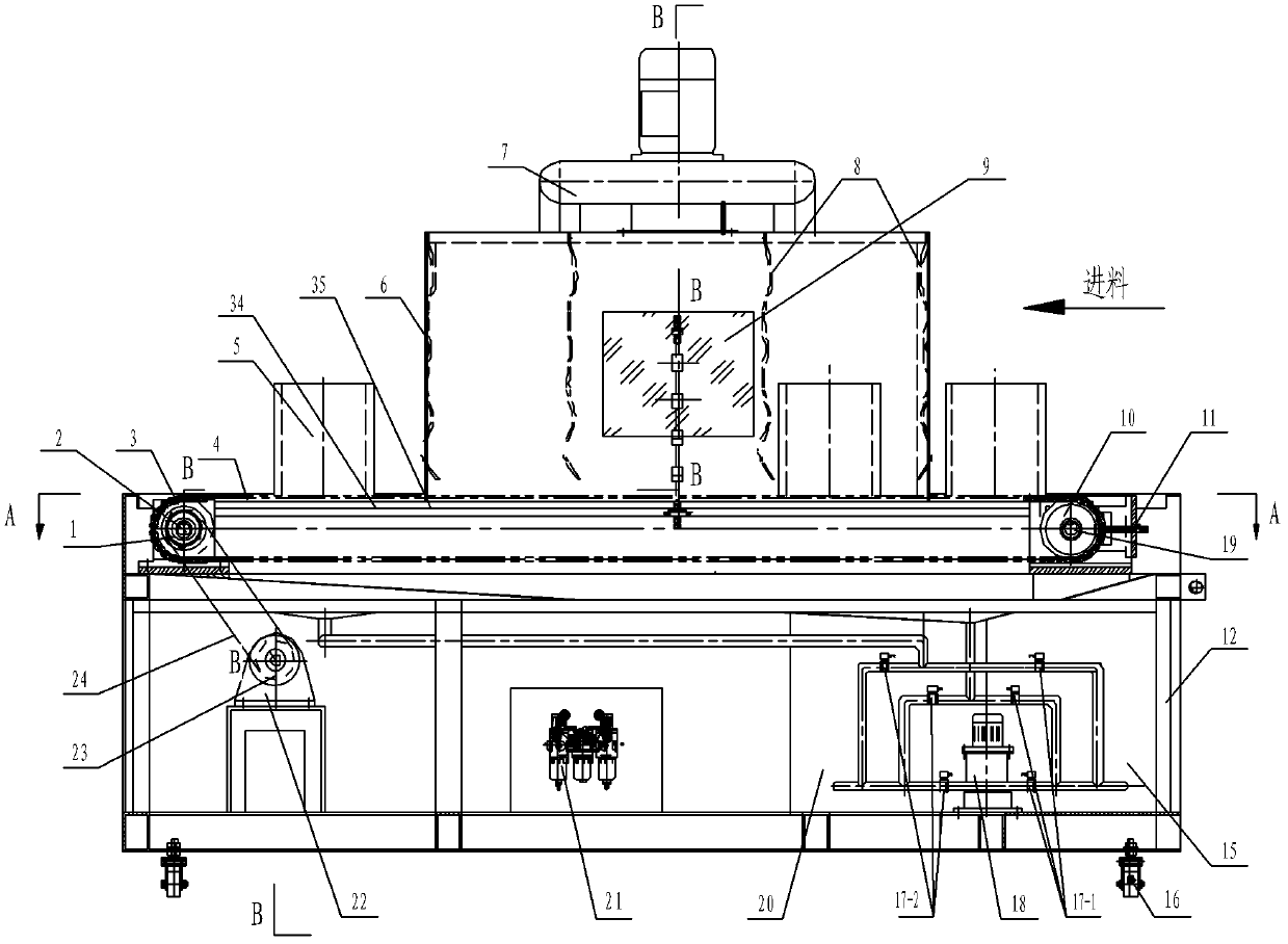
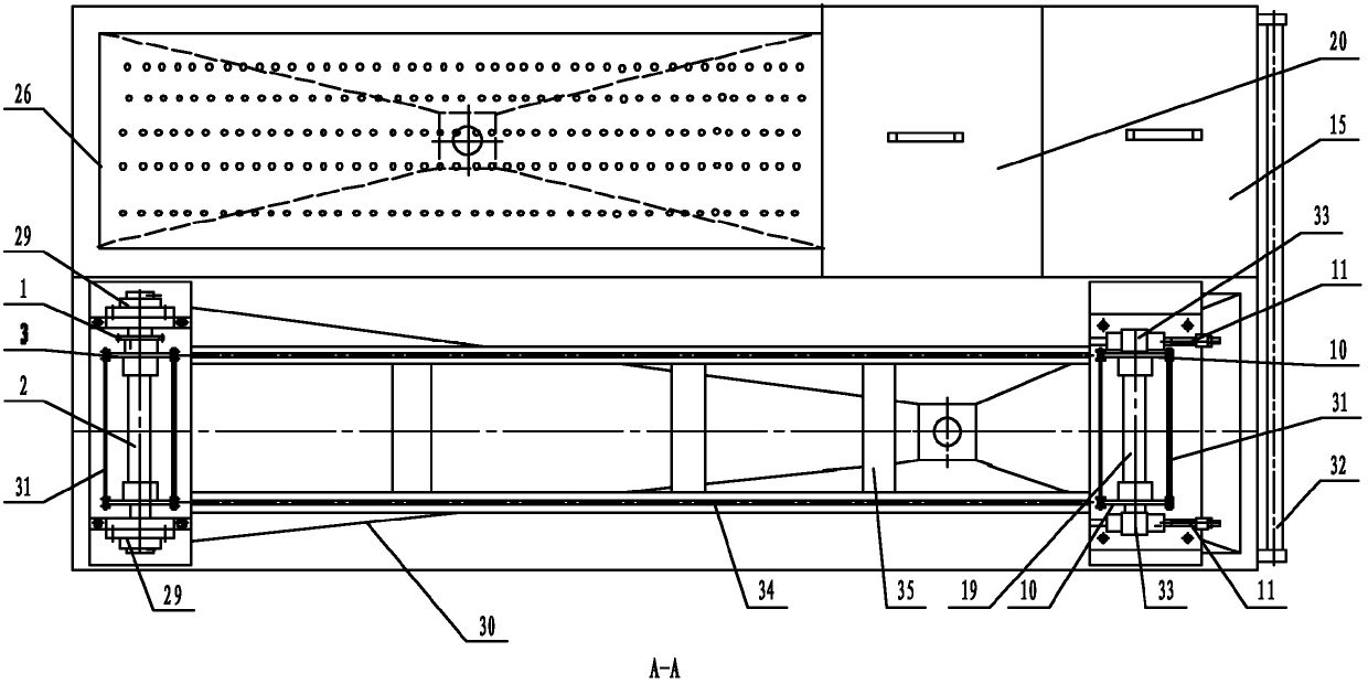
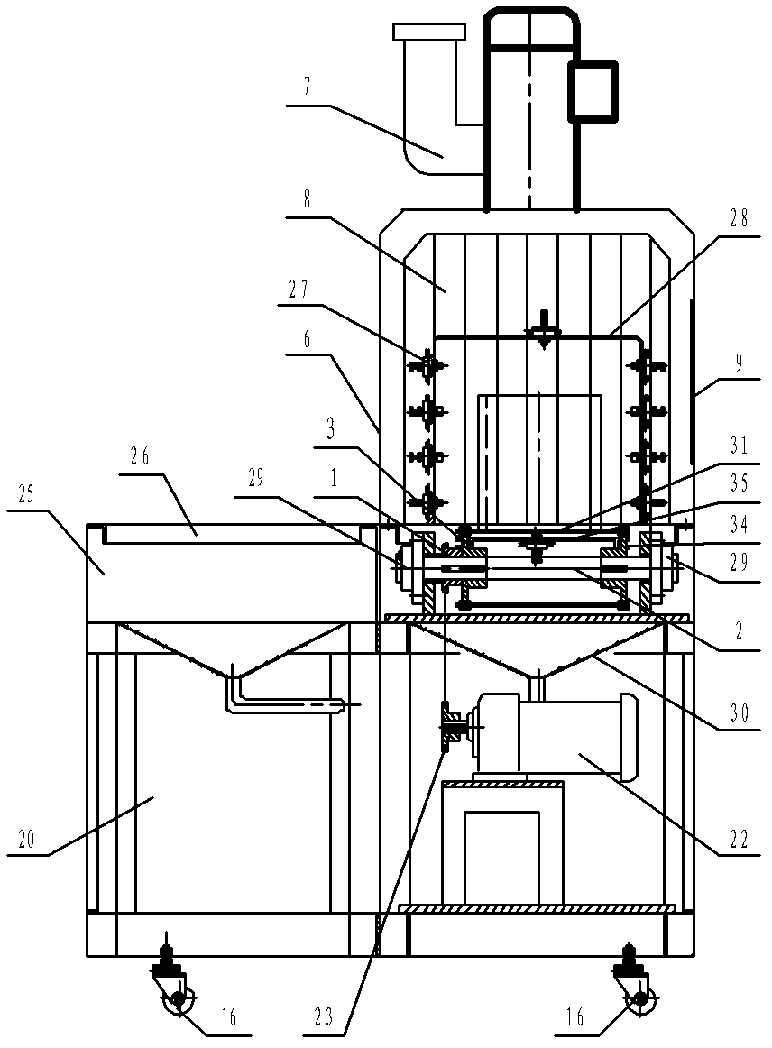
[0021] like Figure 1-3 As shown, the machine includes electrical control system, air source supply device, frame 12, air source treatment part 21, oil mist collector 7, atomizing oil nozzle 27, oil pump 18, oil tank, solenoid valve, chain transmission device and chain Conveyor device; chain transmission device comprises sprocket reducer 22, driving sprocket 23, driven sprocket 1, chain 24, sprocket shaft 2, bearing seat 29 which are arranged on frame 12; driving sprocket 23 is arranged on sprocket On the power output shaft of the speed reducer 22, the driven sprocket 1 is arranged on the power transmission shaft including the sprocket shaft 2 and the bearing seat 29, and the chain 24 is arranged on the driving sprocket 23 and the driven sprocket 1; the chain conveying device includes A pair of conveying sprockets 3, a pair of driven conveying sprockets 10 and a pair of conveying chains 4 arranged on the frame, a pair of conveying sprockets 3 and driven sprockets 1 are arrange...

Embodiment 2

[0028]In this embodiment, one fuel tank in the above-mentioned first embodiment is divided into two independent fuel tanks, and the rest of the structure is the same as that of the first embodiment; Oil, use different types of oil according to different workpieces; in order to make the oil of the same specification recycled to the oil tank of the same specification after use, a three-way pipe is provided on the oil inlet of the oil pump 18, and the set three-way pipe is connected with the oil tank. A solenoid valve 1 17-1 is provided on the pipeline connected with the first 15, and a solenoid valve 17-2 is provided on the pipeline connected with the oil tank 2 20; the oil collection tank 1 25, the oil collection tank 2 30 and the oil mist collector 7 The oil discharge pipes are all provided with three-way pipes, and each of the three-way pipes is respectively provided with a solenoid valve one 17-1 on the pipeline communicated with the fuel tank one 15, and is respectively prov...


PUM


Abstract

The invention relates to a conveyor-type automatic oil mist coating machine, wherein the conveyor-type automatic oil mist coating machine is characterized in that: the coating machine is fixed with a spraying chamber on a frame in the middle of a chain conveyor line; gates of which a workpiece passes in and out are arranged on right and left sides of the spraying chamber; a plurality of atomizing oil nozzles are fixed on an atomizing shelf inside the spraying chamber; an oil mist separator is fixed at the top of the spraying chamber; an inlet of the oil mist separator is communicated with an inner cavity of the spraying chamber; an exhaust port and an oil drainage port are respectively communicated with an exhaust pipe and an oil tank; an air inlet of an air source processing member distributed on the coating machine is communicated with an air source supply device; an outlet of the air source processing member is communicated with the air inlet of each atomizing oil nozzle; an oil inlet of an oil pump distributed on the coating machine is communicated with the oil tank; the oil outlet of the oil pump is communicated with the oil inlet of each atomizing oil nozzle; and the oil outlets of an oil collecting tank arranged below a concave work bench and a conveyer line of the coating machine are respectively communicated with the oil tank. According to the coating machine disclosed by the invention, the automatic degree is high; oil and manpower are saved, and the coating machine can be independently operated and also can form an automatic pipeline together with an interface of a workpiece production line.

Description

technical field [0001] The invention relates to a spraying equipment, in particular to a conveying type oil mist automatic spraying machine which can realize automatic feeding and automatic spraying of oil mist. Background technique [0002] At present, during the manufacturing process of all fuel (gas) engine cylinder liners and other components in China, the protective oil coating process uses manual immersion into containers containing protective oil one by one with hooks, and then takes them out and hangs them on special brackets to pour oil. The sets of workpieces are drained of remaining oil and then sealed and packaged; [0003] The main disadvantages of this process are: 1. It requires a large operating space to achieve mass production; 2. The coating time is long and the production efficiency is low. It takes a long time to wait for a workpiece to be sealed from the time it is immersed in oil until it can be sealed and packaged. 3. High oil consumption and easy pol...

Claims


Application Information

Patent Timeline
Patent Type & Authority Applications(China)
IPC IPC(8): B05B13/02B05B15/04B05B15/06B05B15/12
Inventor 吕年标
Owner 盐城新时代智能检测设备制造厂
Learn More