Combined type transformer for photovoltaic power generation

A combined transformer and photovoltaic power generation technology, applied to transformers, fixed transformers, circuits, etc., can solve the problems of long maintenance and replacement requirements, increased fuel tank volume, increased oil consumption, etc., to ensure safe and normal operation, replacement, etc. Simplified work and reduced fuel consumption

Active Publication Date: 2012-07-18
NINGBO TIANAN GRP CO LTD
View PDF7 Cites 11 Cited by
  • Summary
  • Abstract
  • Description
  • Claims
  • Application Information

AI Technical Summary

Problems solved by technology

This type of transformer dedicated to photovoltaic power generation can only convert the voltage level of a single photovoltaic generator; however, my country's photovoltaic power generation industry is developing rapidly, and the scale of photovoltaic power generation continues to grow, so it has developed a transformer that can convert two or more photovoltaic generators And the combined transformer that can operate normally will have good application value
[0004] In addition, the existing combined transformers for photovoltaic power generation in China require the installation of high-voltage fuses to protect the equipment, and oil-immersed plug-in high-voltage fuses are usually used to achieve this function; As the volume increases, the inner space of the oil tank must be filled with transformer oil, and the corresponding oil consumption is greatly increased; the use of oil-immersed plug-in high-voltage fuses will also cause problems such as difficult sealing, long time for inspection, maintenance and replacement, etc.

Method used


Image

  • Combined type transformer for photovoltaic power generation
  • Combined type transformer for photovoltaic power generation
  • Combined type transformer for photovoltaic power generation

Examples


Embodiment Construction

[0019] In order to describe the present invention more specifically, the technical solutions of the present invention will be described in detail below in conjunction with the accompanying drawings and specific embodiments.

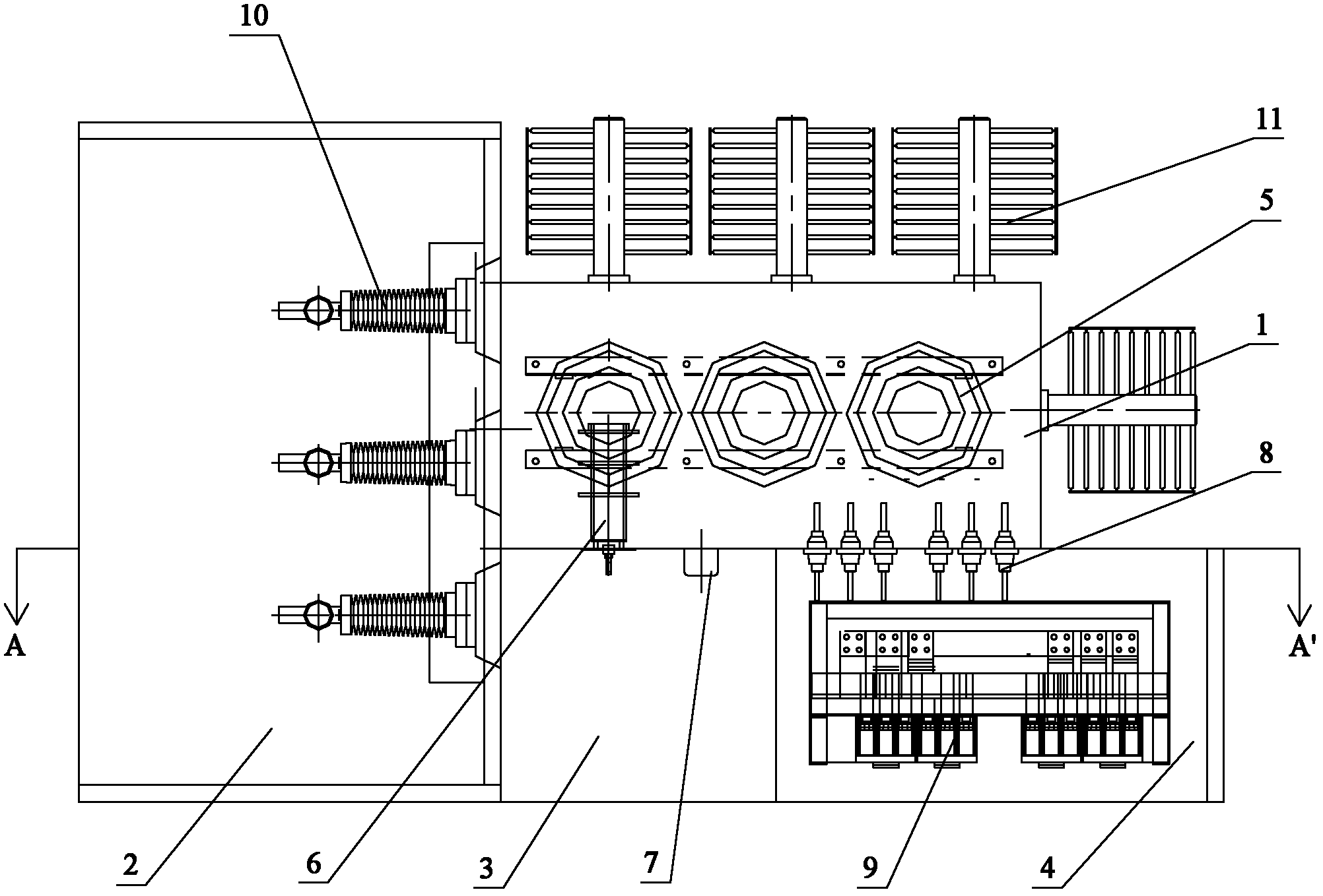
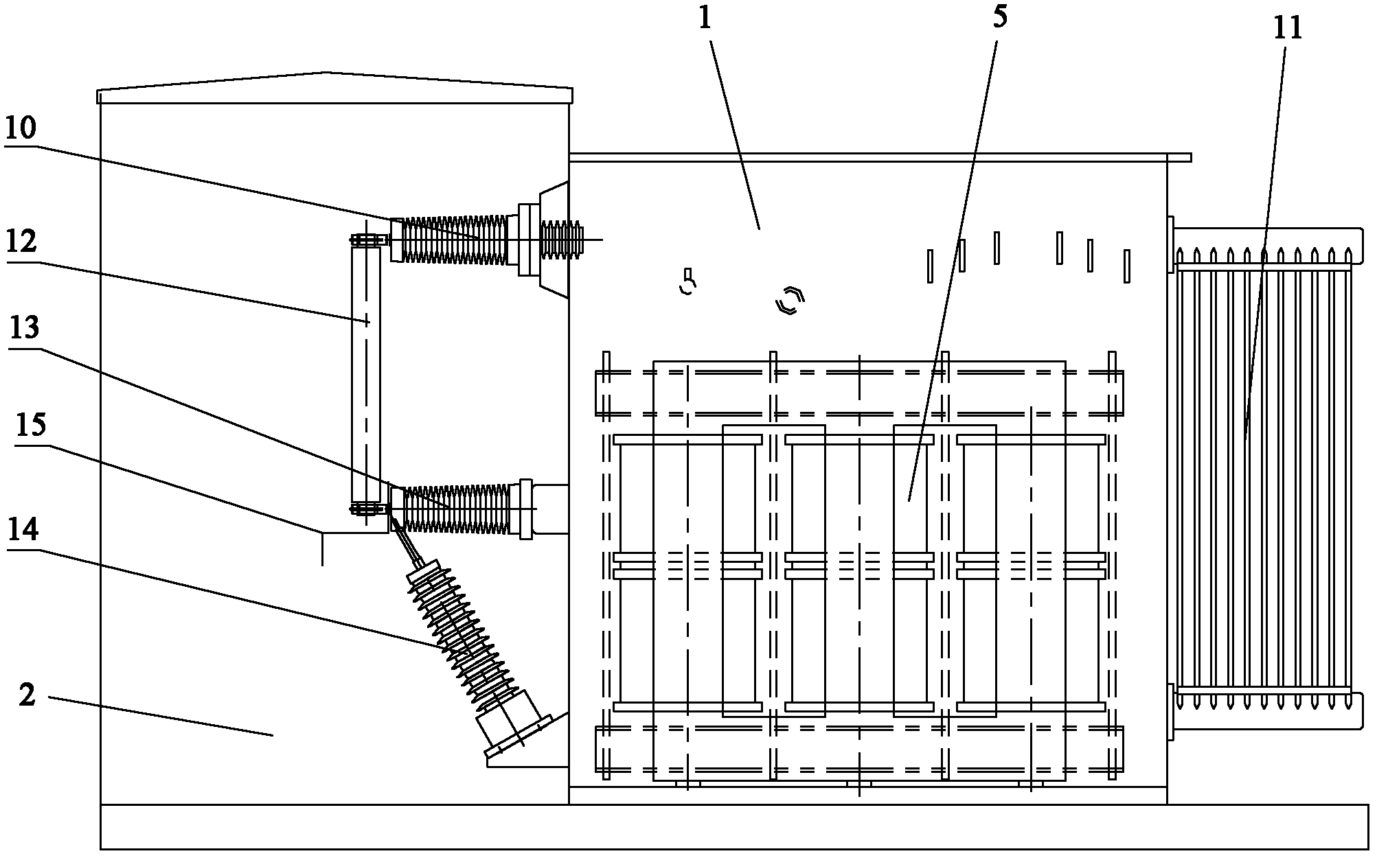
[0020] Such as figure 1 with figure 2 As shown, a combined transformer for photovoltaic power generation includes a transformer oil tank 1; the left side of the transformer oil tank 1 is provided with a high-voltage cable room 2, and the front side is provided with a high-voltage operation room 3 and a low-voltage operation room 4; a high-voltage cable room 2, a high-voltage The operating room 3 and the low-voltage operating room 4 are respectively made into a box body, and are connected with the transformer oil tank 1 through bolts to form a whole.

[0021] The transformer oil tank 1 is provided with an axial double-split three-phase transformer 5 and a high-voltage load switch 6 and a tap changer 7 connected to the high-voltage side of the axial doubl...


PUM


Abstract

The invention discloses a combined type transformer for photovoltaic power generation. The combined type transformer comprises a transformer oil tank, a high-voltage cable chamber, a high-voltage operation chamber and a low-voltage operation chamber; the transformer oil tank is internally provided with an axial double split type three-phase transformer, a high-voltage load switch and a tapping switch; the low-voltage operation chamber is internally provided with a low-voltage switch cabinet; and the high-voltage cable chamber is provided with a high-voltage fuse. According to the invention, an oil immersion insertion type high-voltage fuse which has large volume of outline and is convenient to maintain in an original transformer oil tank is omitted, and the external high-voltage fuse is adopted to effectively reduce inner space of the oil tank and reduce inner oil consumption and corresponding high-voltage connecting wires; and meanwhile, the axial double split type three-phase transformer is adopted to realize that one combined type transformer can perform voltage class transformation on two photovoltaic power generators at the same time, thus, the installation space is saved, the cost is reduced, and the safety normal operation of a power grid and equipment is guaranteed.

Description

technical field [0001] The invention belongs to the technical field of transformer design and manufacture, and in particular relates to a combined transformer for photovoltaic power generation. Background technique [0002] The combined transformer for photovoltaic power generation is used on the outlet side of the photovoltaic generator to increase the voltage from low voltage to high voltage and then merge into the grid; for example, the combined transformer for photovoltaic power generation of 35KV generally boosts the voltage from 0.27KV to 35KV Connect to the main transformer or merge into the power grid. [0003] The Chinese patent with the publication number CN102360832A discloses a step-up transformer for photovoltaic power generation. The transformer includes an iron core, a coil and a clamp. ; The low-voltage coil is wound together by two independent coils radially at the same time. This type of dedicated transformer for photovoltaic power generation can only con...

Claims


Application Information

Patent Timeline
Patent Type & Authority Applications(China)
IPC IPC(8): H02B5/00H02B1/18H01F30/06H01F27/40H02B1/04
Inventor 朱永利郑瑞宏何俊伟梁哲明仇宏海周真珍
Owner NINGBO TIANAN GRP CO LTD
Why Eureka
Try Eureka