
Tunnel vacuum drying equipment

A technology of vacuum drying equipment and tunnels, which is applied in the direction of drying solid materials, progressive dryers, lighting and heating equipment, etc., and can solve the problems of not saving energy, taking a long time, and not being fully utilized.

Inactive Publication Date: 2012-07-18
山东润工自动化设备有限公司
View PDF5 Cites 17 Cited by
  • Summary
  • Abstract
  • Description
  • Claims
  • Application Information

AI Technical Summary

Problems solved by technology

The rapid expansion of the production capacity of the lithium battery industry has led to the rapid development of the lithium battery production equipment manufacturing industry. Energy saving and consumption reduction is the key to the development of lithium battery vacuum drying equipment. The energy shortage has attracted the attention of the whole world. Electric heating lithium battery vacuum drying equipment technology is to put the vacuum box into the heat preservation oven for welding and fixing, and use electric heating to blow hot air to heat the surface of the vacuum box from normal temperature to high temperature. After the electric heating tube is powered off, the vacuum box is kept warm Standing in the oven for natural cooling from high temperature to normal temperature, the oven takes a long time to heat and cool the vacuum box during production, and consumes a lot of power, resulting in a long production cycle for a single process, and repeated heating of the oven during batch cycle production and cooling, resulting in loss of heat energy, which cannot be fully utilized and does not save energy

Method used


Image

  • Tunnel vacuum drying equipment
  • Tunnel vacuum drying equipment

Examples


Embodiment Construction

[0010] The present invention will be further described below in conjunction with accompanying drawing and specific embodiment:

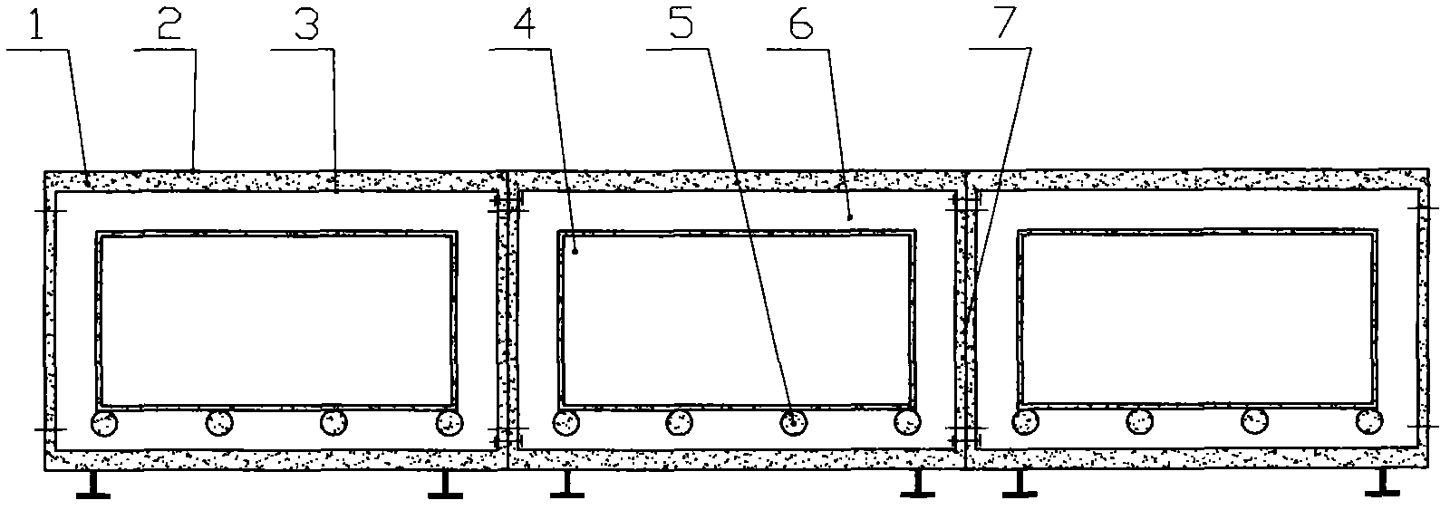
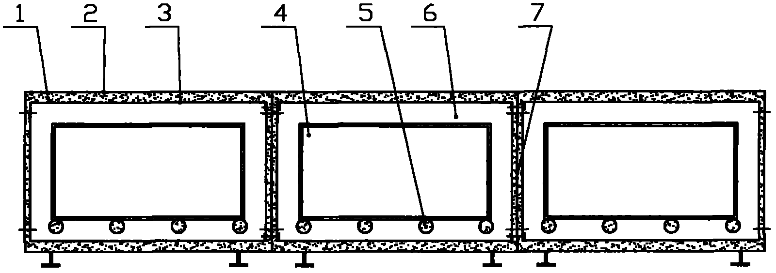
[0011] A tunnel vacuum drying equipment, such as figure 1 As shown, it includes: an outer shell 2, an inner tank 3 is fixedly connected inside the outer shell 2, an insulating material 1 is filled between the inner tank 3 and the outer shell 2, an isolation door 7 is connected to the two ends of the outer shell 2 and the inner tank 3, and the inner cavity 6 is equipped with an air inlet and outlet, a steam heating device and a condensed water cooling device, and a temperature control device is installed on the inner cavity 6, and a roller 5 is connected to the inner cavity 6, and a vacuum box 4 is connected to the roller 5. The box body 4 is equipped with a sealed door, and the vacuum box body 4 is fixedly connected with a pipeline, and a valve is installed on the pipeline; two or more tunnel vacuum drying equipment are used together.

[0012] When ...


PUM


Abstract

The invention discloses tunnel vacuum drying equipment, which comprises a shell, wherein a liner is fixedly connected in the shell; a thermal insulation material is filled between the liner and the shell; two ends of the shell and the liner are connected with isolating doors; an air inlet / outlet is formed and a steam heating device and a condensate water cooling device are arranged on an inner cavity; a temperature control device is arranged on the inner cavity; rollers are connected in the inner cavity; vacuum box bodies are connected on the rollers and are provided with sealing doors; pipelines are fixedly connected on the vacuum box bodies; valves are arranged on the pipelines; and two or more pieces of tunnel vacuum drying equipment are matched. Materials to be dried can be strictly controlled according to process flows and are subjected to monitoring management and production in a centralized mode in batches by stages, and the quality of products can be guaranteed; meanwhile, manual labor and workshop space are saved, fund and energy are saved, and the equipment is environment-friendly.

Description

technical field [0001] The invention relates to a vacuum drying device, in particular to a tunnel vacuum drying device. Background technique [0002] At present, my country's lithium battery is developing rapidly in the new energy industry. From the initial mobile phone lithium battery to the current new energy vehicle power battery, the huge market space has made domestic enterprises involved in the field of new energy batteries spring up in recent years. From a few factories in the late 1990s to more than 400 factories now, the huge market prospect has led most companies to announce capacity expansion plans. The rapid expansion of the production capacity of the lithium battery industry has led to the rapid development of the lithium battery production equipment manufacturing industry. Energy saving and consumption reduction is the key to the development of lithium battery vacuum drying equipment. The energy shortage has attracted the attention of the whole world. Electric ...

Claims


Application Information

Patent Timeline
Patent Type & Authority Applications(China)
IPC IPC(8): F26B15/12F26B7/00H01M10/058
CPCY02E60/12Y02E60/10Y02P70/50
Inventor 陈东华
Owner 山东润工自动化设备有限公司
Learn More